5.2. The von Neumann Architecture
The von Neumann architecture serves as the foundation for most modern computers. In this section, we briefly characterize the architecture’s major components.
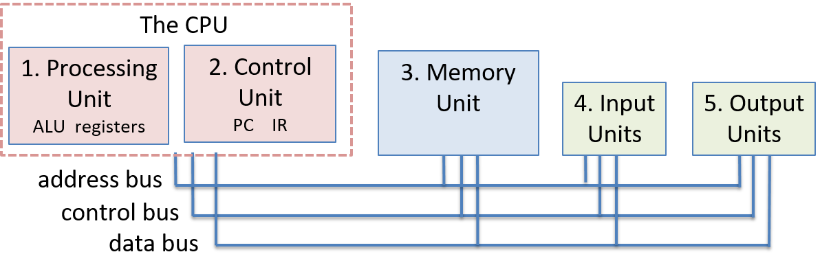
The von Neumann architecture (depicted in Figure 1) consists of five main components:
-
The processing unit executes program instructions.
-
The control unit drives program instruction execution on the processing unit. Together, the processing and control units make up the CPU.
-
The memory unit stores program data and instructions.
-
The input unit(s) load program data and instructions on the computer and initiate program execution.
-
The output unit(s) store or receive program results.
Buses connect the units, and are used by the units to send control and data information to one another. A bus is a communication channel that transfers binary values between communication endpoints (the senders and receivers of the values). For example, a data bus that connects the memory unit and the CPU could be implemented as 32 parallel wires that together transfer a 4-byte value, 1-bit transferred on each wire. Typically, architectures have separate buses for sending data, memory addresses, and control between units. The units use the control bus to send control signals that request or notify other units of actions, the address bus to send the memory address of a read or write request to the memory unit, and the data bus to transfer data between units.
5.2.1. The CPU
The control and processing units together implement the CPU, which is the part of the computer that executes program instructions on program data.
5.2.2. The Processing Unit
The processing unit of the von Neumann machine consists of two parts. The first is the arithmetic/logic unit (ALU), which performs mathematical operations such as addition, subtraction, and logical or, to name a few. Modern ALUs typically perform a large set of arithmetic operations. The second part of the processing unit is a set of registers. A register is a small, fast unit of storage used to hold program data and the instructions that are being executed by the ALU. Crucially, there is no distinction between instructions and data in the von Neumann architecture. For all intents and purposes, instructions are data. Each register is therefore capable of holding one data word.
5.2.3. The Control Unit
The control unit drives the execution of program instructions by loading them from memory and feeding instruction operands and operations through the processing unit. The control unit also includes some storage to keep track of execution state and to determine its next action to take: the program counter (PC) keeps the memory address of the next instruction to execute, and the instruction register (IR) stores the instruction, loaded from memory, that is currently being executed.
5.2.4. The Memory Unit
Internal memory is a key innovation of the von Neumann architecture. It provides program data storage that is close to the processing unit, significantly reducing the amount of time to perform calculations. The memory unit stores both program data and program instructions — storing program instructions is a key part of the stored-program model of the von Neumann architecture.
The size of memory varies from system to system. However, a system’s ISA limits the range of addresses that it can express. In modern systems, the smallest addressable unit of memory is one byte (8 bits), and thus each address corresponds to a unique memory location for one byte of storage. As a result, 32-bit architectures typically support a maximum address space size of 232, which corresponds to 4 gigabytes (GiB) of addressable memory.
The term memory sometimes refers to an entire hierarchy of storage in the system. It can include registers in the processing unit as well as secondary storage devices like hard disk drives (HDD) or solid-state drives (SSD). In the Storage and Memory Hierarchy Chapter, we discuss the memory hierarchy in detail. For now, we use the term "memory" interchangeably with internal random access memory (RAM) — memory that can be accessed by the central processing unit. RAM storage is random access because all RAM storage locations (addresses) can be accessed directly. It is useful to think of RAM as a linear array of addresses, where each address corresponds to one byte of memory.
5.2.5. The Input and Output (I/O) Units
While the control, processing, and memory units form the foundation of the computer, the input and output units enable it to interact with the outside world. In particular, they provide mechanisms for loading a program’s instructions and data into memory, storing its data outside of memory, and displaying its results to users.
The input unit consists of the set of devices that enable a user or program to get data from the outside world into the computer. The most common forms of input devices today are the keyboard and mouse. Cameras and microphones are other examples.
The output unit consists of the set of devices that relay results of computation from the computer back to the outside world or that store results outside internal memory. For example, the monitor is a common output device. Other output devices include speakers and haptics.
Some modern devices, such as the touchscreen, act as both input and output, enabling users to both input and receive data from a single unified device.
Solid-state and hard drives are another example of devices that act as both input and output devices. These storage devices act as input devices when they store program executable files that the operating system loads into computer memory to run, and they act as output devices when they store files to which program results are written.
5.2.6. The von Neumann Machine in Action: Executing a Program
The five units that make up the von Neumann architecture work together to implement a fetch-decode-execute-store cycle of actions that together execute program instructions. This cycle starts with a program’s first instruction, and is repeated until the program exits:
-
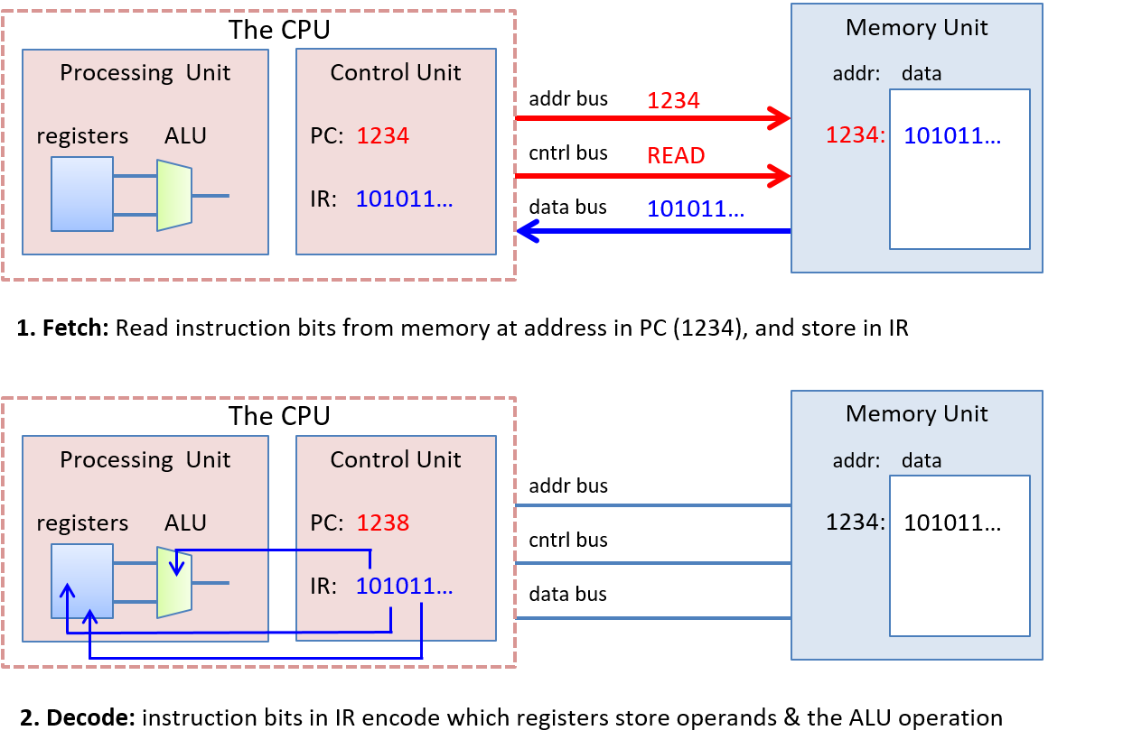
The control unit fetches the next instruction from memory. The control unit has a special register, the program counter (PC), that contains the address of the next instruction to fetch. It places that address on the address bus and places a read command on the control bus to the memory unit. The memory unit then reads the bytes stored at the specified address and sends them to the control unit on the data bus. The instruction register (IR) stores the bytes of the instruction received from the memory unit. The control unit also increments the PC’s value to store the address of the new next instruction to fetch.
-
The control unit decodes the instruction stored in the IR. It decodes the instruction bits that encode which operation to perform and the bits that encode where the operands are located. The instruction bits are decoded based on the ISA’s definition of the encoding of its instructions. The control unit also fetches the data operand values from their locations (from CPU registers, memory, or encoded in the instruction bits), as input to the processing unit.
-
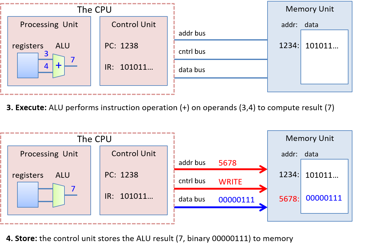
The processing unit executes the instruction. The ALU performs the instruction operation on instruction data operands.
-
The control unit stores the result to memory. The result of the processing unit’s execution of the instruction is stored to memory. The control unit writes the result to memory by placing the result value on the data bus, placing the address of the storage location on the address bus, and placing a write command on the control bus. When received, the memory unit writes the value to memory at the specified address.
The input and output units are not directly involved in the execution of program instructions. Instead, they participate in the program’s execution by loading a program’s instructions and data and by storing or displaying the results of the program’s computation.
Figure 2 and Figure 3 show the four phases of instruction execution by the von Neumann architecture for an example addition instruction whose operands are stored in CPU registers. In the fetch phase, the control unit reads the instruction at the memory address stored in the PC (1234). It sends the address on the address bus, and a READ command on the control bus. The memory unit receives the request, reads the value at address 1234, and sends it to the control unit on the data bus. The control unit places the instruction bytes in the IR register and updates the PC with the address of the next instruction (1238 in this example). In the decode phase, the control unit feeds bits from the instruction that specify which operation to perform to the processing unit’s ALU, and uses instruction bits that specify which registers store operands to read operand values from the processing unit’s registers into the ALU (the operand values are 3 and 4 in this example). In the execute phase, the ALU part of the processing unit executes the operation on the operands to produce the result (3 + 4 is 7). Finally, in the store phase the control unit writes the result (7) from the processing unit to the memory unit. The memory address (5678) is sent on the address bus, a WRITE command is sent on the control bus, and the data value to store (7) is sent on the data bus. The memory unit receives this request and stores 7 at memory address 5678. In this example, we assume that the memory address to store the result is encoded in the instruction bits.