5.4.2. Control Circuits
Control circuits are used throughout a system. On the processor, they drive the execution of program instructions on program data. They also control loading and storing values to different levels of storage (between registers, cache, and RAM), and control hardware devices in the system. Just like arithmetic and logic circuits, control circuits that implement complicated functionality are built by combining simpler circuits and logic gates.
A multiplexer (MUX) is an example of a control circuit that selects, or chooses, one of several values. The CPU may use a multiplexer circuit to select from which CPU register to read an instruction operand value.
An N-way multiplexer has a set of N input values and a single output value selected from one of its inputs. An additional input value, Select (S), encodes which of its N inputs is chosen for its output.
The most basic two-way MUX selects between two 1-bit inputs, A and B. The select input for a two-way multiplexer is a single bit: if the S input is 1, it will select A for output; if it is 0 it will select B for output. The truth table for a two-way 1-bit multiplexer is shown below. The value of the selection bit (S) chooses either the value of A or B as the MUX output value.
| A | B | S | out |
|---|---|---|---|
0 |
0 |
0 |
0 (B’s value) |
0 |
1 |
0 |
1 (B’s value) |
1 |
0 |
0 |
0 (B’s value) |
1 |
1 |
0 |
1 (B’s value) |
0 |
0 |
1 |
0 (A’s value) |
0 |
1 |
1 |
0 (A’s value) |
1 |
0 |
1 |
1 (A’s value) |
1 |
1 |
1 |
1 (A’s value) |
Figure 1 shows the two-way multiplexer circuit for single-bit input.
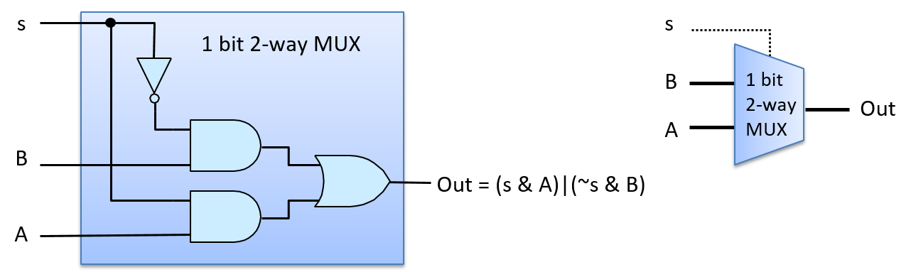
Figure 2 shows how the multiplexer chooses A’s output with an S input value of 1. For example, suppose that the input values are 1 for A, 0 for B, and 1 for S. S is negated before being sent to the top AND gate with B (0 AND B), resulting in a 0 output value from the top AND gate. S feeds into the bottom AND gate with A, resulting in (1 AND A), which evaluates to the value of A being output from the bottom AND gate. The value of A (1 in our example) and 0 from the top AND gate feed as input to the OR gate, resulting in (0 OR A) being output. In other words, when S is 1, the MUX chooses the value of A as its output (A’s value being 1 in our example). The value of B does not affect the final output of the MUX, because 0 will always be the output of the top AND gate when S is 1.
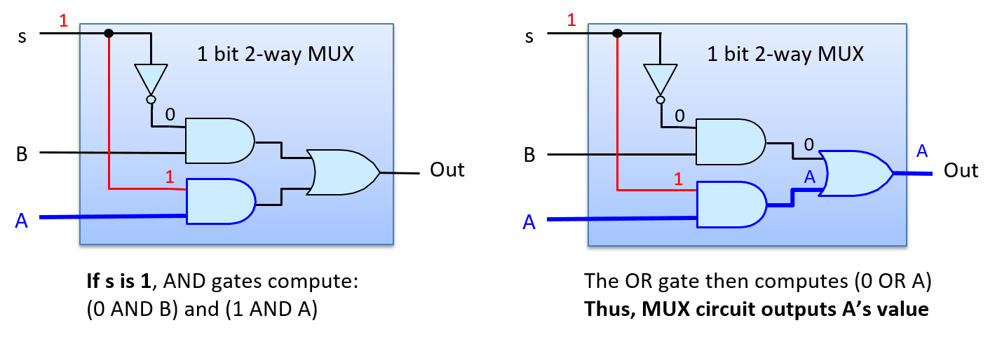
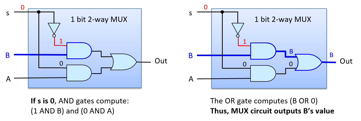
Figure 3 shows the path through the multiplexer when the S input value 0 chooses B’s output. If we consider the same input for A and B as the example above, but change S to 0, then the negation of 0 is input to the top AND gate resulting in (1 AND B), or B’s value, output from the top AND gate. The input to the bottom AND gate is (0 AND A), resulting in 0 from the bottom AND gate. Thus, the input values to the OR gate are (B OR 0), which evaluates to B’s value as the MUX’s output (B’s value being 0 in our example).
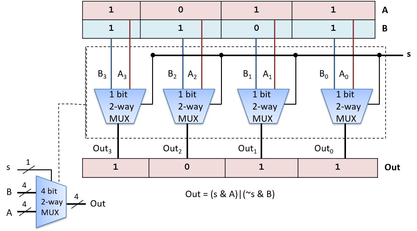
A two-way 1- bit MUX circuit is a building block for constructing two-way N-bit MUX circuits. For example, Figure 4 shows a two-way 4-bit MUX built from four 1-bit two-way MUX circuits.
An N-way multiplexer chooses one of N inputs as output. It requires a slightly different MUX circuit than a two-way MUX, and needs log2(N) bits for its Select input. The additional selection bits are needed because with log2(N) bits, N distinct values can be encoded, one for selecting each of the N inputs. Each distinct permutation of the log2(N) Select bits is input with one of the N input values to an AND gate, resulting in exactly one MUX input value selected as the MUX output. Figure 5 shows an example of a 1-bit four-way MUX circuit.
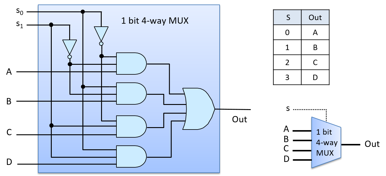
The four-way MUX circuit uses four three-input AND gates and one four-input OR gate. Multi-input versions of gates can be built by chaining together multiple two-input AND (and OR) gates. For example, a three-input AND gate is built from two two-input AND gates, where the first AND gate takes two of the input values and the second AND gate takes the third input value and the output from the first AND gate: (x AND y AND z) is equivalent to ((x AND y) AND z).
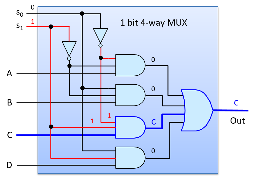
To see how the four-way MUX circuit works, consider an S input value of 2 (0b10 in binary), as shown in Figure 6. The top AND gate gets as input (NOT(S0) AND NOT(S1) AND A), or (1 AND 0 AND A), resulting in 0 output from the top AND gate. The second AND gate gets input values (0 AND 0 AND B), resulting in 0 output. The third AND gate gets input values (1 AND 1 AND C), resulting in the value of C output. The last AND gate gets (0 AND 1 AND D), resulting in 0 output. The OR gate has inputs (0 OR 0 OR C OR 0), resulting in the value of C output by the MUX (an S value of 2 chooses C).
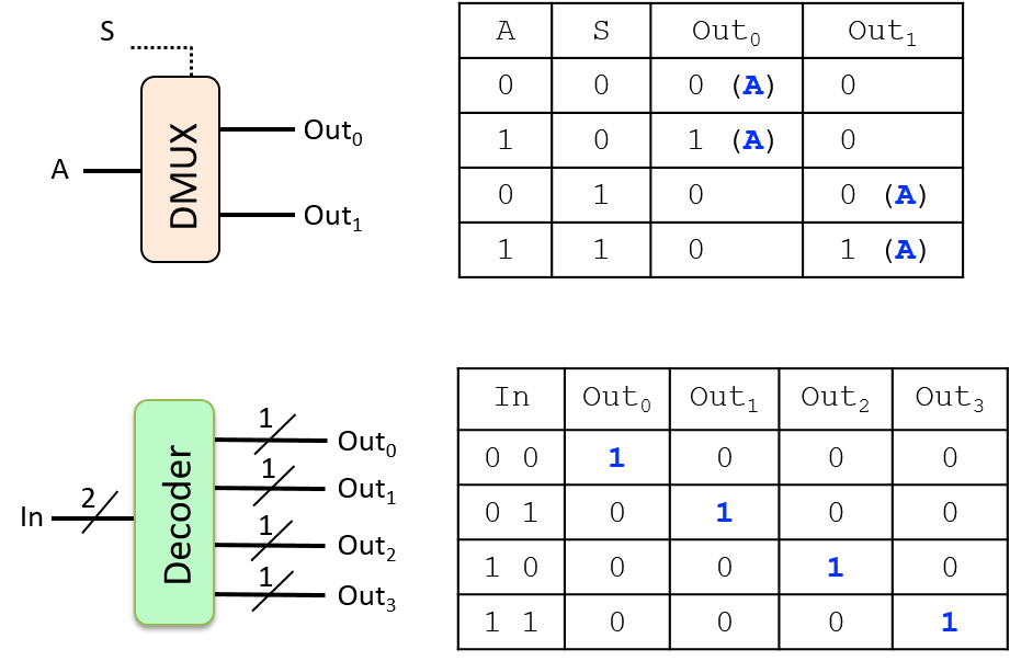
Demultiplexers and decoders are two other examples of control circuits. A demultiplexer (DMUX) is the inverse of a multiplexer. Whereas a multiplexer chooses one of N inputs, a demultiplexer chooses one of N outputs. A DMUX takes a single input value and a selection input, and has N outputs. Based on the value of S, it sends the input value to exactly one of its N outputs (the value of the input is routed on to one of N output lines). A DMUX circuit is often used to select one of N circuits to pass a value. A decoder circuit takes an encoded input and enables one of several outputs based on the input value. For example, a decoder circuit that has an N-bit input value, uses the value to enable (to set to 1) exactly one of its 2N output lines (the one corresponding to the encoding of the N-bit value). Figure 7 Shows an example of a two-way 1-bit DMUX circuit, whose selection input value (s) chooses which of its two outputs gets the input value A. It also shows an example of a 2-bit decoder circuit, whose input bits determine which of four outputs get set to 1. The truth tables for both circuits are also shown.