5.3. Logic Gates
Logic gates are the building blocks of the digital circuitry that implements arithmetic, control, and storage functionality in a digital computer. Designing complicated digital circuits involves employing a high degree of abstraction: a designer creates simple circuits that implement basic functionality from a small set of basic logic gates; these simple circuits, abstracted from their implementation, are used as the building blocks for creating more complicated circuits (simple circuits are combined together to create new circuits with more complicated functionality); these more complicated circuits may be further abstracted and used as a building block for creating even more complicated functionality; and so on to build complete processing, storage, and control components of a processor.
5.3.1. Basic Logic Gates
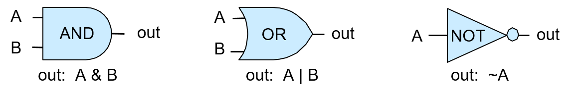
At the lowest level, all circuits are built from linking logic gates together. Logic gates implement boolean operations on boolean operands (0 or 1). AND, OR, and NOT form a complete set of logic gates from which any circuit can be constructed. A logic gate has one (NOT) or two (AND and OR) binary input values and produces a binary output value that is the bitwise logical operation on its input. For example, an input value of 0 to a NOT gate outputs 1 (1 is NOT(0)). A truth table for a logical operation lists the operation’s value for each permutation of inputs. Table 1 shows the truth tables for the AND, OR, and NOT logic gates.
| A | B | A AND B | A OR B | NOT A |
|---|---|---|---|---|
0 |
0 |
0 |
0 |
1 |
0 |
1 |
0 |
1 |
1 |
1 |
0 |
0 |
1 |
0 |
1 |
1 |
1 |
1 |
0 |
Figure 1 shows how computer architects represent these gates in circuit drawings.
A multi-bit version of a logic gate (for M-bit input and output) is a very simple circuit constructed using M one-bit logic gates. Individual bits of the M-bit input value are each input into a different one-bit gate that produces the corresponding output bit of the M-bit result. For example, Figure 2 shows a 4-bit AND circuit built from four 1-bit AND gates.
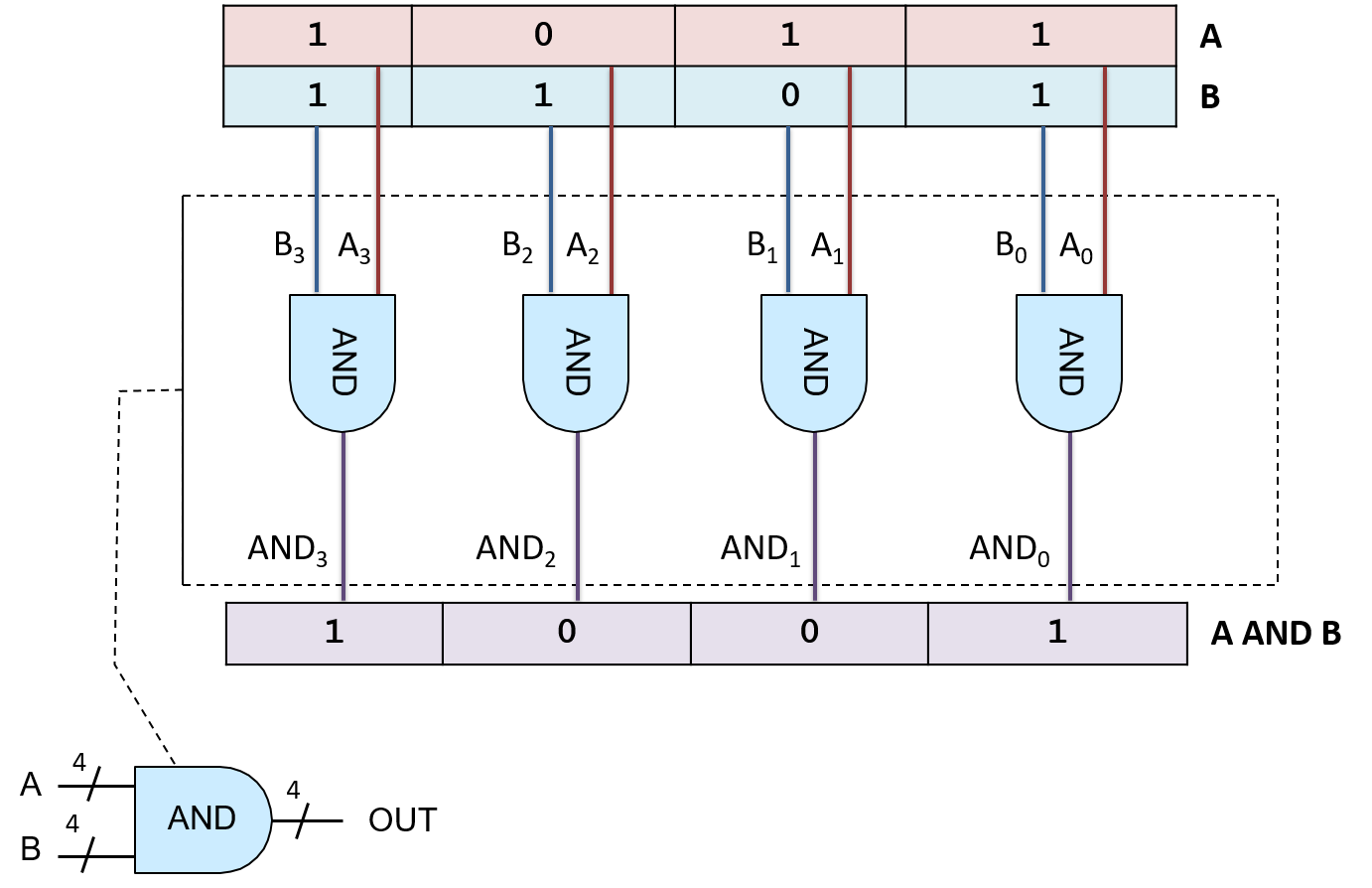
This type of very simple circuit, one that just expands input and output bit width for a logic gate, is often referred to as an M-bit gate for a particular value of M specifying the input and output bit width (number of bits).
5.3.2. Other Logic Gates
Even though the set of logic gates consisting of AND, OR, and NOT is sufficient for implementing any circuit, there are other basic logic gates that are often used to construct digital circuits. These additional logic gates include NAND (the negation of A AND B), NOR (the negation of A OR B), and XOR (exclusive OR). Their truth tables are shown in Table 2.
| A | B | A NAND B | A NOR B | A XOR B |
|---|---|---|---|---|
0 |
0 |
1 |
1 |
0 |
0 |
1 |
1 |
0 |
1 |
1 |
0 |
1 |
0 |
1 |
1 |
1 |
0 |
0 |
0 |
The NAND, NOR, and XOR gates appear in circuit drawings, as shown in Figure 3.
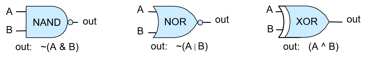
The circle on the end of the NAND and NOR gates represents negation or NOT. For example, the NOR gate looks like an OR gate with a circle on the end, representing the fact that NOR is the negation of OR.
NAND, NOR, and XOR are not necessary for building circuits, but they are additional gates added to the set {AND, OR, NOT} that are commonly used in circuit design. Any of these gates can be implemented from transistors (the building block of logic gates), or can be implemented from combinations of other gates.
Of the larger set {AND, OR, NOT, NAND, NOR, XOR}, there exist several minimal subsets of logic gates that alone are sufficient for building any circuit. For example, the subset {AND, NOT} is one minimal subset: (A OR B) is equivalent to NOT(NOT(A) AND NOT(B)). Rather than using a minimal subset of gates, we we use the set {AND, OR, NOT} because it is the easiest set to understand.
Because NAND, NOR, and XOR are not necessary,
their functionality can be implemented by
combining AND, OR, and NOT gates into circuits that implement NAND, NOR,
and XOR functions. For example, NOR can be built using a NOT combined with
an OR gate, (A NOR B) ≡ NOT(A OR B)), as shown in Figure 4.

Today’s integrated circuits chips are built using CMOS technology, which uses NAND as the basic building block of circuits on the chip. The NAND gate by itself makes up another minimal subset of complete logic gates.