7.2. Common Instructions
In this section, we discuss several common assembly instructions. Table 1 lists the most foundational instructions in x86 (and thus x64) assembly.
| Instruction | Translation |
|---|---|
|
S → D (copies value of S into D) |
|
S + D → D (adds S to D and stores result in D) |
|
D - S → D (subtracts S from D and stores result in D) |
Therefore, the sequence of instructions
mov    -0x4(%rbp),%eax
add    $0x2,%eax
translates to:
-
Copy the value at location
%rbp+ -0x4 in memory (M[%rbp- 0x4]) to register%eax. -
Add the value 0x2 to register
%eax, and store the result in register%eax.
The three instructions shown in Table 1 also form the building blocks for instructions that
maintain the organization of the program stack (i.e., the call stack). Recall that registers %rbp and %rsp refer
to the frame pointer and stack pointer, respectively, and are reserved by the compiler
for call stack management. Recall from our earlier discussion on
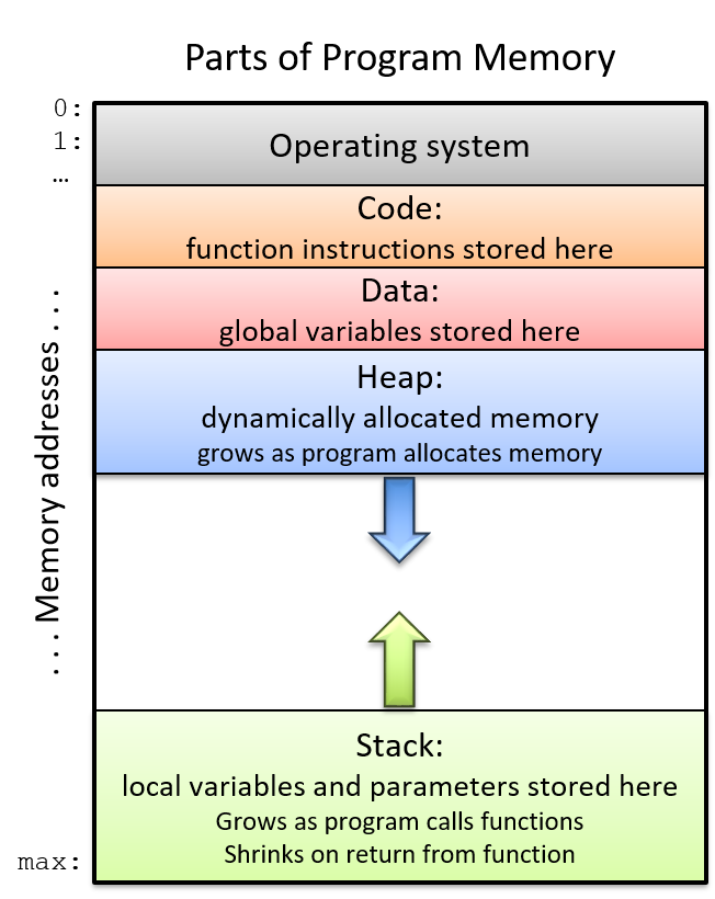
program memory that the
call stack typically stores local variables and parameters and
helps the program track its own execution (see Figure 1). On x86-64 systems, the execution stack grows toward
lower addresses. Like all stack data structures, operations occur at the "top" of the stack.
The x86-64 ISA provides two instructions (Table 2) to simplify call stack management.
Instruction |
Translation |
|
Pushes a copy of S onto the top of the stack. Equivalent to: sub $0x8, %rsp mov S, (%rsp) |
|
Pops the top element off the stack and places it in location D. Equivalent to: mov (%rsp), D add $0x8, %rsp |
Notice that while the three instructions in Table 1 require two operands, the push and pop
instructions in Table 2 require only one operand apiece.
7.2.1. Putting It All Together: A More Concrete Example
Let’s take a closer look at the adder2 function:
//adds two to an integer and returns the result
int adder2(int a) {
    return a + 2;
}
and its corresponding assembly code:
0000000000400526 <adder2>:
  400526:       55                      push   %rbp
  400527:       48 89 e5                mov    %rsp,%rbp
  40052a:       89 7d fc                mov    %edi,-0x4(%rbp)
  40052d:       8b 45 fc                mov    -0x4(%rbp),%eax
  400530:       83 c0 02                add    $0x2,%eax
  400533:       5d                      pop    %rbp
  400534:       c3                      retq
The assembly code consists of a push instruction, followed by three mov
instructions, an add instruction, a pop instruction, and finally a retq instruction. To understand
how the CPU executes this set of instructions, we need to revisit the structure
of program memory.
Recall that every time a program executes, the operating system allocates the new program’s
address space (also known as virtual memory). Virtual memory
and the related concept of processes are covered in greater
detail in Chapter 13; for now, it suffices to think of a process as the abstraction of a
running program and virtual memory as the memory that is allocated to a single process.
Every process has its own region of memory called the call stack. Keep in mind that the call
stack is located in process/virtual memory, unlike registers (which are located on the CPU).
Figure 2 depicts a sample state of the call stack and registers prior to the execution
of the adder2 function.
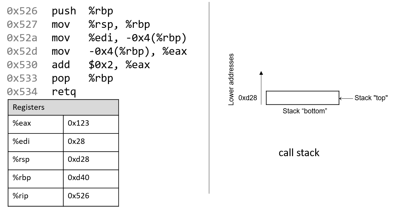
Notice that the stack grows toward lower addresses. Register %eax contains a junk value.
The single parameter to the adder2 function (a) is stored in register %rdi by convention. Since
a is of type int, it is stored in component register %edi, which is shown in Figure 2.
Likewise, since the adder2 function returns an int, component register %eax is used for
the return value instead of %rax.
The addresses associated with the instructions in the code segment of program memory (0x400526-0x400534) have been shortened to (0x526-0x534) to improve figure readability. Likewise, the addresses associated with the call stack segment of program memory have been shortened to 0xd28-0xd1c from 0x7fffffffdd28 - 0x7fffffffdd1c. In truth, call stack addresses occur at much higher addresses in program memory than code segment addresses.
Pay close attention to the initial values of registers %rsp and %rbp: they
are 0xd28 and 0xd40, respectively. The red (upper-left) arrow in the following figures
visually indicates the currently executing instruction. The %rip register
(or instruction pointer) shows the next instruction to execute. Initially,
%rip contains address 0x526, which corresponds to the first instruction in
the adder2 function.
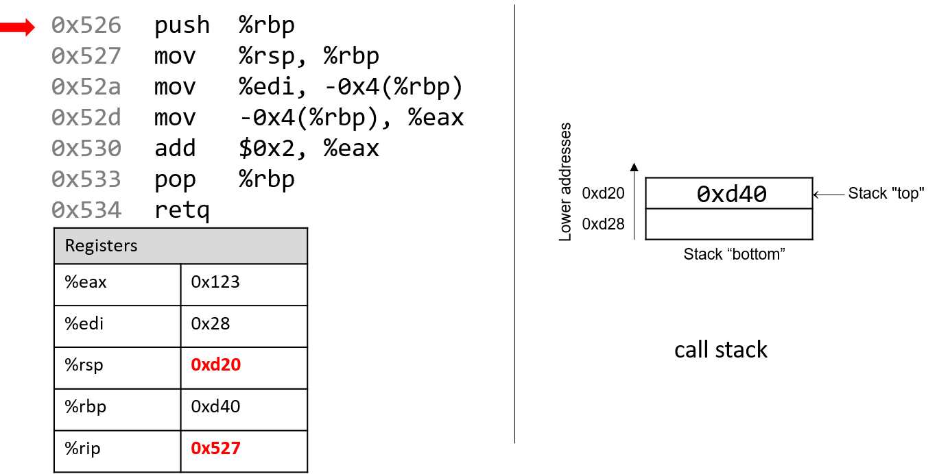
The first instruction (push %rbp) places a copy of the value in %rbp (or 0xd40) on top of the
stack. After it executes, the %rip register advances to the address of the next instruction to
execute (0x527). The push instruction decrements the stack pointer by 8 ("growing" the stack by 8 bytes),
resulting in a new %rsp value of 0xd20. Recall that the push %rbp instruction is equivalent to:
sub $8, %rsp
mov %rbp, (%rsp)
In other words, subtract 8 from the stack pointer and place a copy of the contents of %rbp
in the location pointed to by the dereferenced stack pointer, (%rsp).
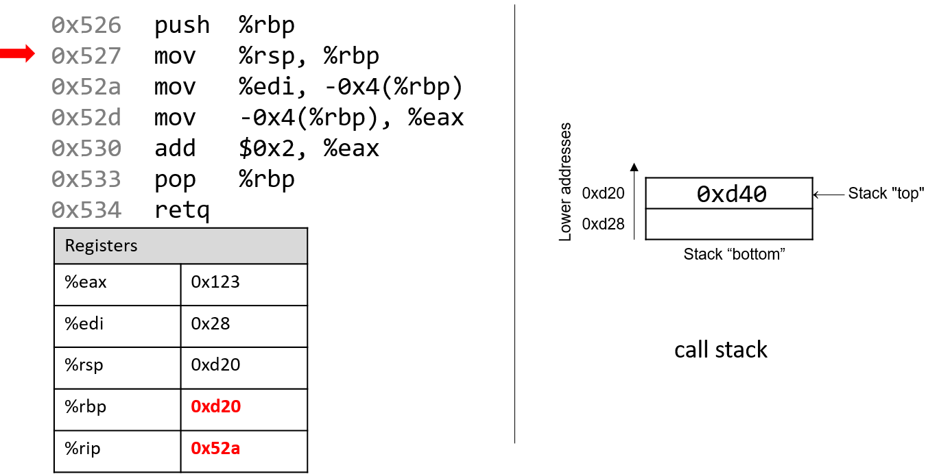
Recall that the structure of the mov instruction is mov S,D, where S is the source location,
and D is the destination. Thus, the next instruction (mov %rsp, %rbp) updates the value of
%rbp to 0xd20. The register %rip advances to the address of the next instruction to execute,
or 0x52a.
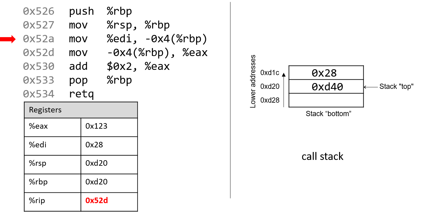
Next, mov %edi, -0x4(%rbp) is executed. This is a bit more complicated
than the last mov instruction. Let’s parse it piece by piece. First, recall that
the first parameter to any function is stored in register %rdi. Since a is of
type int, the compiler stores the first parameter in component register %edi.
Next, the operand -0x4(%rbp) translates to
M[%rbp - 0x4]. Since %rbp contains the value 0xd20, subtracting
4 from it yields 0xd1c. Therefore, the mov instruction
copies the value of register %edi (or 0x28) to location 0xd1c on the stack.
The instruction pointer advances to address 0x52d, the next address to be executed.
Note that storing the value 0x28 does not affect the stack pointer (%rsp).
Therefore, as far as the program is concerned, the "top" of this stack is still
address 0xd20.
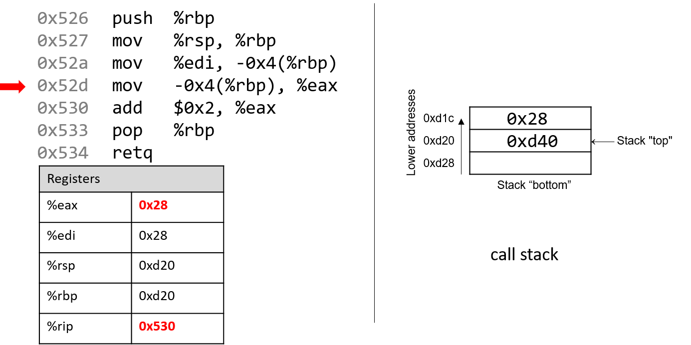
The next mov instruction (mov -0x4(%rbp), %eax) copies the value at stack
location 0xd1c (i.e., M[%rbp - 0x4] or 0x28) and stores it in register %eax.
Register %rip advances to the next instruction to be executed, or 0x530.
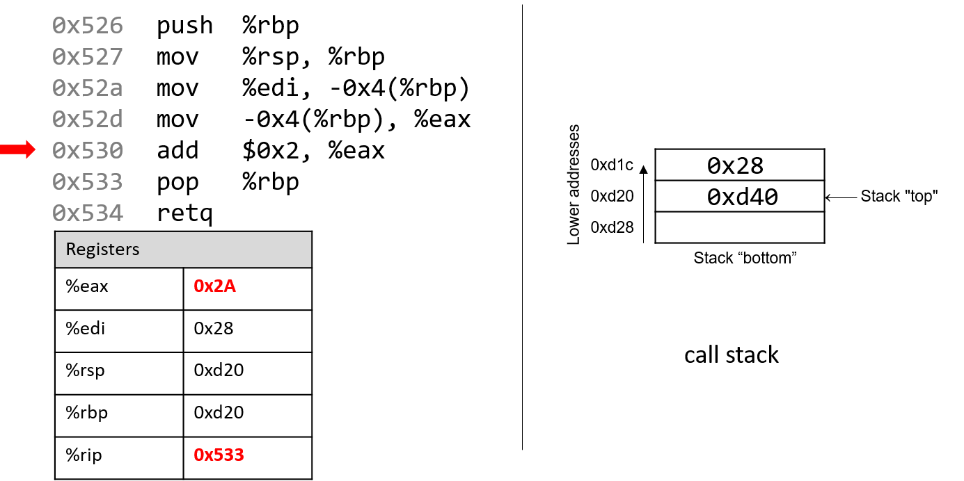
Next, add $0x2, %eax is executed. Recall that the add instruction
has the form add S,D and places the quantity S + D in the destination D. So,
add $0x2, %eax adds the constant value 0x2 to the value stored in %eax
(or 0x28), resulting in the value 0x2A being stored in register %eax. Register
%rip advances to point to the next instruction to be executed, or 0x533.
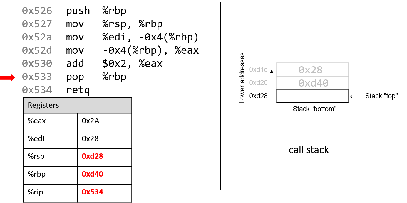
The next instruction that executes is pop %rbp. This instruction "pops"
the value off the top of the call stack and places it in destination register %rbp.
Recall that this instruction is equivalent to the following sequence of
two instructions:
mov (%rsp), %rbp
add $8, %rsp
Recall that the top of the stack is 0xd20, since that is the value stored in
%rsp. Therefore, once this instruction executes, the value (%rsp)
(i.e., M[0xd20]) is copied into register %rbp. Thus, %rbp now contains
the value 0xd40. The stack pointer increments by 8, since the stack
grows toward lower addresses (and consequently shrinks toward higher ones).
The new value of %rsp is 0xd28, and %rip now points to the address of
the last instruction to execute (i.e., 0x534).
The last instruction executed is retq. We will talk more about what
happens with retq in future sections when we discuss function calls, but
for now it suffices to know that it prepares the call stack for returning from a
function. By convention, the register %rax always contains the return value
(if one exists). In this case, because adder2 is of type int, the return
value is stored in component register %eax, and the function returns the
value 0x2A, or 42.
Before we continue, note that the final values in registers %rsp and %rbp are
0xd28 and 0xd40, respectively, which are the same values as when the function
started executing! This is normal and expected behavior with the call
stack. The purpose of the call stack is to store the temporary variables and data
of each function as it executes in the context of a program. Once a function
completes executing, the stack returns to the state it was in prior to the
function call. As a result, it is common to see the following two
instructions at the beginning of a function:
push %rbp
mov %rsp, %rbp
and the following two instructions at the end of a function:
pop %rbp
retq