5.8. Advanced Pipelined Instruction Considerations
Recall that pipelining improves the performance of a processor by overlapping the execution of multiple instructions. In our earlier discussion on pipelining, we described a simple four-stage pipeline with the basic stages of Fetch (F), Decode (D), Execute (E) and WriteBack (W). In our discussion that follows, we also consider a fifth stage, Memory (M), which represents an access to data memory. Our five-stage pipeline therefore comprises the following stages:
-
Fetch (F): reads an instruction from memory (pointed to by the program counter).
-
Decode (D): reads source registers and sets control logic.
-
Execute (E): executes the instruction.
-
Memory (M): reads from or writes to data memory.
-
WriteBack (W): stores a result in a destination register.
Recall that the compiler transforms lines of code into a series of machine code instructions for the CPU to execute. Assembly code is a human-readable version of machine code. The snippet below displays a series of made-up assembly instructions:
MOV M[0x84], Reg1     # move value at memory address 0x84 to register Reg1
ADD 2, Reg1, Reg1     # add 2 to value in Reg1 and store result in Reg1
MOV 4, Reg2           # copy the value 4 to register Reg2
ADD Reg2, Reg2, Reg2  # compute Reg2 + Reg2, store result in Reg2
JMP L1<0x14>          # jump to executing code at L1 (code address 0x14)
Don’t worry if you are having trouble parsing the snippet — we cover assembly in greater detail in upcoming chapters. For now, it suffices to focus on the following set of facts:
-
Every ISA defines a set of instructions.
-
Each instruction operates on one or more operands (i.e. registers, memory, or constant values).
-
Not all instructions require the same number of pipeline stages to execute.
In our previous discussion, it was assumed that every instruction takes the
same number of cycles to execute; however, this is usually not the case. For
example, the first MOV instruction requires all five stages, as it requires
the movement of data from memory to a register. In contrast, the next three
instructions require only four stages (F, D, E, W) to execute given that the
operations involve only registers, and not memory. The last instruction
(JMP) is a type of branch or conditional instruction. Its purpose is to
transfer the flow of control to another part of the code. Specifically,
addresses in the code region of memory reference different instructions in an
executable. Since the JMP instruction does not update a general-purpose
register, the WriteBack stage is omitted, resulting in only three stages (F, D,
E) being required. We cover conditional instructions in greater detail in the
upcoming
chapters on assembly.
A pipeline stall results when any instruction is forced to wait for another to finish executing before it can continue. Compilers and processors do whatever they can to avoid pipeline stalls in order to maximize performance.
5.8.1. Pipelining Consideration: Data Hazards
A data hazard occurs when two instructions attempt to access common data in an instruction pipeline. As an example, consider the first pair of instructions from the code snippet above:
MOV M[0x84], Reg1     # move value at memory address 0x84 to register Reg1
ADD 2, Reg1, Reg1     # add 2 to value in Reg1 and store result in Reg1

Recall that this MOV instruction requires five stages (as it involves an
access to memory), whereas the ADD instruction requires only four. In this
scenario, both instructions will attempt to write to register Reg1 at the
same time (see Figure 1).
The processor prevents the aforementioned scenario by first forcing every
instruction to take five pipeline stages to execute. For instructions that
normally take fewer than five stages, the CPU adds a "no-operation" (NOP)
instruction (also called a pipeline "bubble") to substitute for that phase.
However, the problem is still not fully resolved. Since the goal of the second
instruction is to add 2 to the value stored in register Reg1, the MOV
instruction needs to finish writing to register Reg1 before the ADD
instruction can execute correctly. A similar problem exists in the next two
instructions:
MOV 4, Reg2           # copy the value 4 to register Reg2
ADD Reg2, Reg2, Reg2  # compute Reg2 + Reg2, store result in Reg2

These two instructions load the value 4 into register Reg2 and then
multiply it by 2 (by adding to itself). Once again, bubbles are added to
enforce that each instruction takes five pipeline stages. In this case,
regardless of the bubbles, the second instruction’s execute phase occurs
before the first instruction finishes writing the required value (4) to
register Reg2.
Adding more bubbles is a suboptimal solution, because it stalls the pipeline.
Instead, processors employ a technique called operand forwarding, in which
the pipeline reads the result from the previous operation. Looking at
Figure 2, while the instruction MOV 4, Reg2 executes, it forwards its results
to the instruction ADD Reg2, Reg2, Reg2. So, while the MOV instruction is
writing to register Reg2, the ADD instruction can use the updated value of
Reg2 that it received from the MOV instruction.
5.8.2. Pipelining Hazards: Control Hazards
The pipeline is optimized for instructions that occur one after another.
Control changes in a program arising from conditionals such as if statements
or loops can seriously affect the pipeline performance. Let’s take a look at a
different example code snippet, first in C:
int result = *x; // x holds an int
int temp = *y;   // y holds another int

if (result <= temp) {
	result = result - temp;
}
else {
	result = result + temp;
}
return result;
This snippet simply reads integer data from two different pointers, compares the values, and then does different arithmetic based on the result. Here is how the above code snippet may translate into assembly instructions:
  MOV M[0x84], Reg1     # move value at memory address 0x84 to register Reg1
  MOV M[0x88], Reg2     # move value at memory address 0x88 to register Reg2
  CMP Reg1, Reg2        # compare value in Reg1 to value in Reg2
  JLE L1<0x14>          # switch code execution to L1 if Reg1 less than Reg2
  ADD Reg1, Reg2, Reg1  # compute Reg1 + Reg2, store result in Reg1
  JMP L2<0x20>          # switch code execution to L2 (code address 0x20)
L1:
  SUB Reg1, Reg2, Reg1  # compute Reg1 - Reg2, store in Reg1
L2:
  RET                   # return from function
This sequence of instructions loads data from memory into two separate
registers, compares the values, and then does different arithmetic based on
whether the value in the first register is less than the value in the second. The
if statement is represented in the above example with two instructions: the
compare (CMP) instruction and a conditional jump less than (JLE)
instruction. We cover conditional instructions in greater detail in the
upcoming
assembly chapters; for now it is sufficient to understand that the CMP
instruction compares two registers, while the JLE instruction is a special
type of branch instruction that switches code execution to another part of the
program if and only if the condition (i.e. less than or equal, in this case)
is true.
|
Don’t get overwhelmed by the details!
Looking at assembly for the first time can be understandably intimidating. If this is how you feel, try not to worry! We cover assembly in much greater detail in coming chapters. The key takeaway is that code containing conditional statements translates to a series of assembly instructions just like any other code snippet. However, unlike other code snippets, conditional statements are not guaranteed to execute in a particular way. The uncertainty surrounding how a conditional statement executes has large ramifications for the pipeline. |
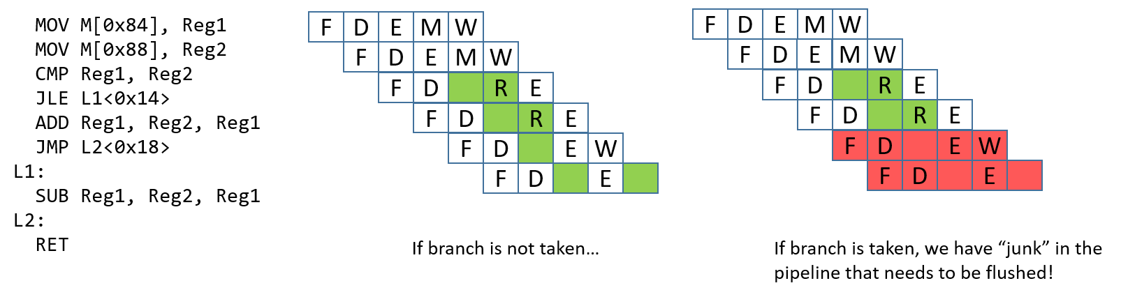
A control hazard occurs when the pipeline encounters a branch (or
conditional) instruction. When this happens, the pipeline has to "guess"
whether the branch will be taken. If the branch is not taken, the process
continues to execute the next instructions in sequence. Consider the example in
Figure 3. If the branch is taken, the next instruction that executes
should be the SUB instruction. However, it is impossible to know whether the
branch is taken until the JLE instruction finishes executing. At that point,
the ADD and JMP instructions have already been loaded into the pipeline.
If the branch is taken, these "junk" instructions in the pipeline need to be
removed, or flushed, before the pipeline can be reloaded with new
instructions. Flushing the pipeline is expensive.
There are a few options that hardware engineers can choose to implement to help the processor deal with control hazards:
-
Stall the pipeline: As a simple solution, whenever there is a branch, add lots of
NOPbubbles and stall the pipeline until the processor is sure that the branch is taken. Although stalling the pipeline will fix the issue, it will also lead to a performance hit (see Figure 4). -
Branch prediction: The most common solution is to use a branch predictor, which will predict which way a branch will go, based on previous executions. Modern branch predictors are really good and accurate. However, this approach has recently caused some security vulnerabilities (e.g. Spectre1). Figure 4 depicts how a branch predictor may deal with the control hazard discussed.
-
Eager execution: In eager execution, the CPU executes both sides of the branch and performs a conditional transfer of data rather than control (implemented through the cmov and the csel instructions in x86 and ARMv8-A, respectively). A conditional transfer of data enables the processor to continue execution without disrupting the pipeline. However, not all code is capable of taking advantage of eager execution, which can be dangerous in the case of pointer dereferences and side effects.

References
-
Peter Bright. Google: Software is never going to be able to fix Spectre-type bugs Ars Technica 2019.