7.1. Diving into Assembly: Basics
For a first look at x64 assembly, we modify the adder function from Chapter 6
to simplify its behavior. The modified function (adder2) is shown below:
#include <stdio.h>

//adds two to an integer and returns the result
int adder2(int a) {
    return a + 2;
}

int main(void){
    int x = 40;
    x = adder2(x);
    printf("x is: %d\n", x);
    return 0;
}
To compile this code, use the following command:
$ gcc -o adder adder.c
Next, let’s view the corresponding assembly of this code by using the
objdump command:
$ objdump -d adder > output
$ less output
Search for the code snippet associated with adder2 by typing /adder2 while examining
the file output using less. The section associated with adder2 should look
similar to the following:
adder2 function0000000000400526 <adder2>: 400526: 55 push %rbp 400527: 48 89 e5 mov %rsp,%rbp 40052a: 89 7d fc mov %edi,-0x4(%rbp) 40052d: 8b 45 fc mov -0x4(%rbp),%eax 400530: 83 c0 02 add $0x2,%eax 400533: 5d pop %rbp 400534: c3 retq
Don’t worry if you don’t understand what’s going on just yet. We will cover assembly in greater detail in later sections. For now, let’s study the structure of these individual instructions.
Each line in the preceding example contains an instruction’s 64-bit address in
program memory, the bytes corresponding to the instruction, and the plaintext
representation of the instruction itself. For example, 55 is the machine code
representation of the instruction push %rbp, and the instruction occurs at address
0x400526 in program memory. Note that 0x400526 is an abbreviation of the
full 64-bit address associated with the push %rbp instruction; the leading
zeroes are ignored for readability.
It is important to note that a single line of C code often translates to multiple
instructions in assembly. The operation a + 2 is represented by the two instructions
mov -0x4(%rbp), %eax and add $0x2, %eax.
|
Your assembly may look different!
If you are compiling your code along with us, you may notice that some of your assembly examples look different from what is shown in this book. The precise assembly instructions that are output by any compiler depend on that compiler’s version and the underlying operating system. Most of the assembly examples in this book were generated on systems running Ubuntu or Red Hat Enterprise Linux (RHEL). In the examples that follow, we do not use any optimization flags. For example,
we compile any example file ( |
7.1.1. Registers
Recall that a register is a word-sized storage unit located directly on the CPU. There may be separate registers for data, instructions, and addresses. For example, the Intel CPU has a total of 16 registers for storing 64-bit data:
%rax, %rbx, %rcx, %rdx, %rdi, %rsi, %rsp, %rbp, and %r8-%r15.
All the registers save for %rsp and %rbp hold general-purpose 64-bit data.
While a program may interpret a register’s contents as, say, an integer or an address, the register itself makes no
distinction. Programs can read from or write to all sixteen registers.
The registers %rsp and %rbp are known as the stack pointer and the frame pointer
(or base pointer), respectively. The compiler reserves these registers for operations that
maintain the layout of the program stack. For example, register %rsp always points to the
top of the stack. In earlier x86 systems (e.g., IA32), the frame pointer commonly tracked
the base of the active stack frame and helped to reference parameters. However, the base pointer is less
frequently used in x86-64 systems. Compilers typically store the first six parameters in registers
%rdi, %rsi, %rdx, %rcx, %r8 and %r9, respectively. Register %rax stores the return value from a function.
The last register worth mentioning is %rip or the instruction pointer,
sometimes called the program counter (PC). It points to the next instruction to be executed by the CPU. Unlike the
16 registers mentioned previously, programs cannot write directly to register %rip.
7.1.2. Advanced Register Notation
Since x86-64 is an extension of the 32-bit x86 architecture (which itself was an extension of an earlier 16-bit version), the ISA provides mechanisms to access the lower 32 bits, 16 bits, and lower bytes of each register. Table 1 lists each of the 16 registers and the ISA notations to access their component bytes.
| 64-bit Register | 32-bit Register | Lower 16 Bits | Lower 8 Bits |
|---|---|---|---|
|
|
|
|
|
|
|
|
|
|
|
|
|
|
|
|
|
|
|
|
|
|
|
|
|
|
|
|
|
|
|
|
|
|
|
|
|
|
|
|
|
|
|
|
|
|
|
|
|
|
|
|
|
|
|
|
|
|
|
|
|
|
|
|
The first eight registers (%rax, %rbx, %rcx, %rdx, %rdi, %rsi, %rsp, and %rbp)
are 64-bit extensions of 32-bit registers in x86 and have a common mechanism for accessing their lower 32 bits, lower 16 bits,
and least-significant byte. To access the lower 32 bits of the first eight registers, simply replace
the r in the register name with e. Thus, the register corresponding to the
lower 32 bits of register %rax is register %eax. To access the lower 16 bits of each of these
eight registers, reference the last two letters of the register’s name. So, the mechanism to access
the lower two bytes of register %rax is %ax.
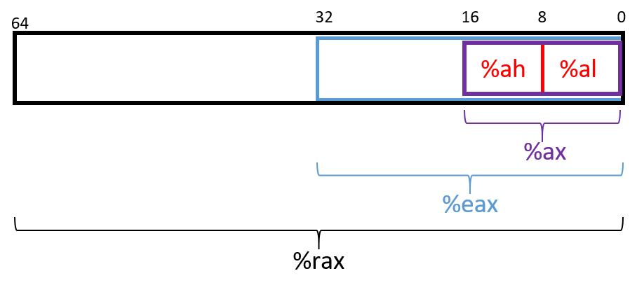
The ISA provides a separate mechanism to access the eight-bit components within
the lower 16 bits of the first four listed registers. Figure 1 depicts the
access mechanisms for register %rax. The higher and lower bytes within
the lower 16 bits of the first four listed registers can be accessed by taking
the last two letters of the register name and replacing the last letter with
either an h (for higher) or an l (for lower) depending on which byte is
desired. For example, %al references the lower eight-bits of register %ax,
whereas %ah references the higher eight-bits of register %ax. These eight-bit
registers are commonly used for storing single-byte values for certain
operations, such as bitwise shifts (a 32-bit register cannot be shifted more
than 32 places, and the number 32 requires only a single byte of storage).
|
Compiler may choose component registers depending on type
When reading assembly code, keep in mind that the compiler typically uses the 64-bit
registers when dealing with 64-bit values (e.g., pointers or |
The last eight registers (%r8-%r15) were not part of the IA32 ISA. However, they also have mechanisms
to access their different byte components. To access the lower 32 bits, 16 bits, or byte of
the last eight registers, append the letter d, w, or b, respectively, to the end of the register’s name. Thus,
%r9d accesses the lower 32 bits of register %r9, whereas %r9w accesses the lower
16 bits, and %r9b accesses the lowest byte of register %r9.
7.1.3. Instruction Structure
Each instruction consists of an operation code (or opcode) that specifies what it
does, and one or more operands that tell the instruction how to do it. For example,
the instruction add $0x2, %eax has the opcode add and the operands $0x2 and %eax.
Each operand corresponds to a source or destination location for a specific operation.
Two operand instructions typically follow the source, destination (S, D) format, where the first
operand specifies a source register, and the second operand specifies the destination.
There are multiple types of operands:
-
Constant (literal) values are preceded by the
$sign. For example, in the instructionadd $0x2, %eax,$0x2is a literal value that corresponds to the hexadecimal value 0x2. -
Register forms refer to individual registers. The instruction
mov %rsp, %rbpspecifies that the value in the source register (%rsp) should be copied to the destination location (register%rbp). -
Memory forms correspond to some value inside main memory (RAM) and are commonly used for address lookups. Memory address forms can contain a combination of registers and constant values. For example, in the instruction
mov -0x4(%rbp),%eax, the operand-0x4(%rbp)is an example of a memory form. It loosely translates to "add -0x4 to the value in register%rbp(i.e., subtract 0x4 from%rbp), and then perform a memory lookup." If this sounds like a pointer dereference, that’s because it is!
7.1.4. An Example with Operands
The best way to explain operands in detail is to present a quick example. Suppose that memory contains the following values:
| Address | Value |
|---|---|
0x804 |
0xCA |
0x808 |
0xFD |
0x80c |
0x12 |
0x810 |
0x1E |
Let’s also assume that the following registers contain the values shown:
| Register | Value |
|---|---|
%rax |
0x804 |
%rbx |
0x10 |
%rcx |
0x4 |
%rdx |
0x1 |
Then the operands in Table 2 evaluate to the values shown there. Each row of the table matches an operand with its form (e.g., constant, register, memory), how it is translated, and its value. Note that the notation M[x] in this context denotes the value at the memory location specified by address x.
| Operand | Form | Translation | Value |
|---|---|---|---|
%rcx |
Register |
%rcx |
0x4 |
(%rax) |
Memory |
M[%rax] or M[0x804] |
0xCA |
$0x808 |
Constant |
0x808 |
0x808 |
0x808 |
Memory |
M[0x808] |
0xFD |
0x8(%rax) |
Memory |
M[%rax + 8] or M[0x80c] |
0x12 |
(%rax, %rcx) |
Memory |
M[%rax + %rcx] or M[0x808] |
0xFD |
0x4(%rax, %rcx) |
Memory |
M[%rax + %rcx + 4] or M[0x80c] |
0x12 |
0x800(,%rdx,4) |
Memory |
M[0x800 + %rdx*4] or M[0x804] |
0xCA |
(%rax, %rdx, 8) |
Memory |
M[%rax + %rdx*8] or M[0x80c] |
0x12 |
In Table 2, the notation %rcx indicates the value stored in register
%rcx. In contrast, M[%rax] indicates that the value inside %rax should be
treated as an address, and to dereference (look up) the value at that address.
Therefore, the operand (%rax) corresponds to M[0x804] which corresponds to
the value 0xCA.
A few important notes before continuing. Although Table 2 shows many valid operand forms, not all forms can be used interchangeably in all circumstances. Specifically:
-
Constant forms cannot serve as destination operands.
-
Memory forms cannot serve as both the source and destination operand in a single instruction.
-
In cases of scaling operations (see the last two operands in Table 2), the scaling factor is a third parameter in the parentheses. Scaling factors can be one of 1, 2, 4, or 8.
Table 2 is provided as a reference; however, understanding key operand forms will help improve the reader’s speed in parsing assembly language.
7.1.5. Instruction Suffixes
In several cases in upcoming examples, common and arithmetic instructions have a suffix that indicates the size (associated with the type) of the data being operated on at the code level. The compiler automatically translates code to instructions with the appropriate suffix. Table 3 shows the common suffixes for x86-64 instructions.
| Suffix | C Type | Size (bytes) |
|---|---|---|
b |
|
1 |
w |
|
2 |
l |
|
4 |
s |
|
4 |
q |
|
8 |
d |
|
8 |
Note that instructions involved with conditional execution have different suffixes based on the evaluated condition. We cover instructions associated with conditional execution in a later section.