11.4. CPU Caches
Having characterized storage devices and recognized the important patterns of temporal and spatial locality, we’re ready to explore how CPU caches are designed and implemented. A cache is a small, fast storage device on a CPU that holds limited subsets of main memory. Caches face several important design questions:
-
Which subsets of a program’s memory should the cache hold?
-
When should the cache copy a subset of a program’s data from main memory to the cache, or vice versa?
-
How can a system determine whether a program’s data is present in the cache?
Before exploring these challenging questions, we need to introduce some cache behavior and terminology. Recall that when accessing data in memory, a program first computes the data’s memory address. Ideally, the data at the desired address already resides in the cache, allowing the program to skip accessing main memory altogether. To maximize performance, the hardware simultaneously sends the desired address to both the cache and main memory. Because the cache is faster and closer to the ALU, the cache responds much more quickly than memory. If the data is present in the cache (a cache hit), the cache hardware cancels the pending memory access because the cache can serve the data faster than memory.
Otherwise, if the data isn’t in the cache (a cache miss), the CPU has no choice but to wait for memory to retrieve it. Critically though, when the request to main memory completes, the CPU loads the retrieved data into the cache so that subsequent requests for the same address (which are likely thanks to temporal locality) can be serviced quickly from the cache. Even if the memory access that misses is writing to memory, the CPU still loads the value into the cache on a miss because it’s likely that the program will attempt to access the same location again in the future.
When loading data into a cache after a miss, a CPU often finds that the cache doesn’t have enough free space available. In such cases, the cache must first evict some resident data to make room for the new data that it’s loading in. Because a cache stores subsets of data copied from main memory, evicting cached data that has been modified requires the cache to update the contents of main memory prior to evicting data from the cache.
To provide all the aforementioned functionality, cache designers employ one of three designs. This section begins by examining direct-mapped caches, which are less complex than the other designs.
11.4.1. Direct-Mapped Caches
A direct-mapped cache divides its storage space into units called cache lines. Depending on the size of a cache, it might hold dozens, hundreds, or even thousands of cache lines. In a direct-mapped cache, each cache line is independent of all the others and contains two important types of information: a cache data block and metadata.
-
A cache data block (often shortened to cache block) stores a subset of program data from main memory. Cache blocks store multibyte chunks of program data to take advantage of spatial locality. The size of a cache block determines the unit of data transfer between the cache and main memory. That is, when loading a cache with data from memory, the cache always receives a chunk of data the size of a cache block.
Cache designers balance a trade-off in choosing a cache’s block size. Given a fixed storage budget, a cache can store more smaller blocks or fewer larger blocks. Using larger blocks improves performance for programs that exhibit good spatial locality, whereas having more blocks gives a cache the opportunity to store a more diverse subset of memory. Ultimately, which strategy provides the best performance depends on the workload of applications. Because general-purpose CPUs can’t assume much about a system’s applications, a typical CPU cache today uses middle-of-the-road block sizes ranging from 16 to 64 bytes.
-
Metadata stores information about the contents of the cache line’s data block. A cache line’s metadata does not contain program data. Instead, it maintains bookkeeping information for the cache line (for example, to help identify which subset of memory the cache line’s data block holds).
When a program attempts to access a memory address, a cache must know where to look to find the corresponding data, check whether the desired data is available at that cache location, and if so, retrieve a portion of the stored cache block to the requesting application. The following steps walk through the details of this process for finding data in a cache and retrieving it.
Locating Cached Data
A cache must be able to quickly determine whether the subset of memory corresponding to a requested address currently resides in the cache. To answer that question, a cache must first determine which cache line(s) to check. In a direct-mapped cache, each address in memory corresponds to exactly one cache line. This restriction explains the direct-mapped name — it maps every memory address directly to one cache line.
Figure 1 shows how memory addresses map to cache lines in a small direct-mapped cache with four cache lines and a 32-byte cache block size. Recall that a cache’s block size represents the smallest unit of data transfer between a cache and main memory. Thus, every memory address falls within one 32-byte range, and each range maps to one cache line.
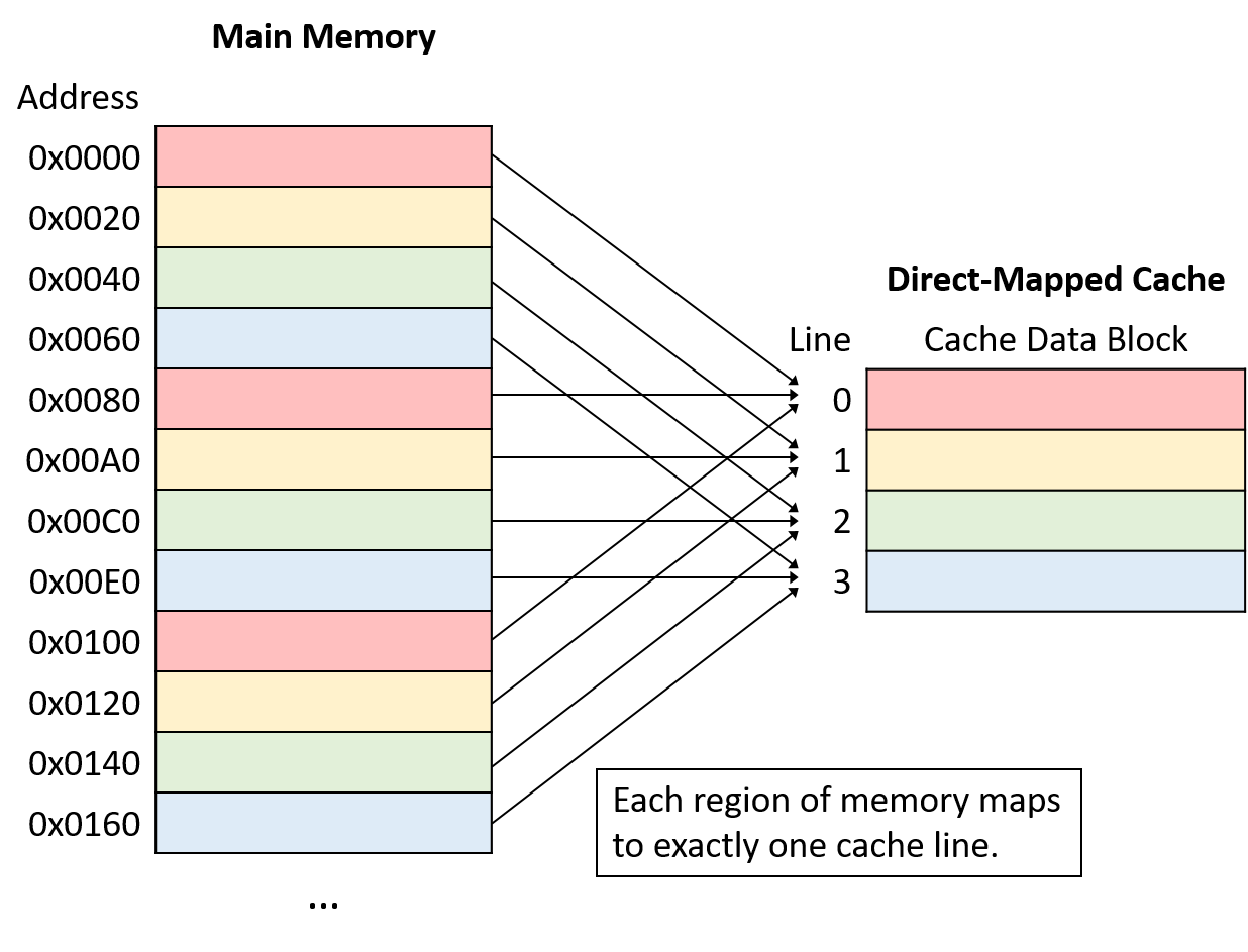
Note that although each region of memory maps to only one cache line, many memory ranges map to the same cache line. All of the memory regions that map the same cache line (that is, chunks of the same color in Figure 1) compete for space in the same cache line, so only one region of each color can reside in the cache at a time.
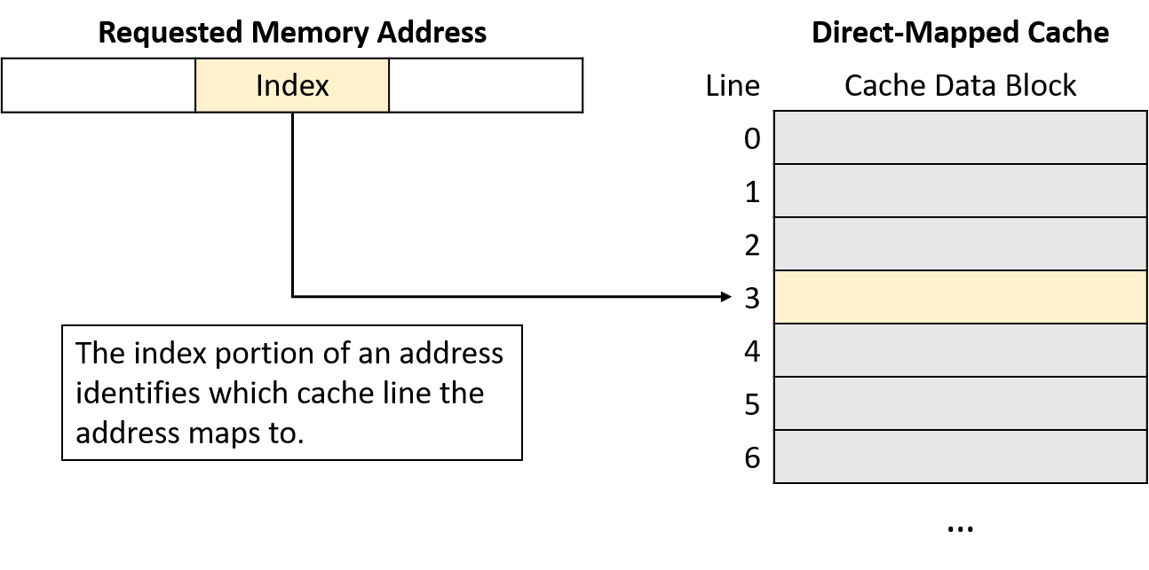
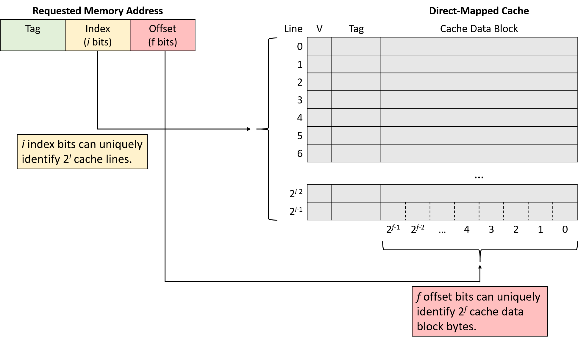
A cache maps a memory address to a cache line using a portion of the bits in the memory address. To spread data more evenly among cache lines, caches use bits taken from the middle of the memory address, known as the index portion of the address, to determine which line the address maps to. The number of bits used as the index (which varies) determines how many lines a cache will hold. Figure 2 shows the index portion of a memory address referring to a cache line.
Using the middle of the address reduces competition for the same cache line when program data is clustered together, which is often the case for programs that exhibit good locality. That is, programs tend to store variables nearby one another in one of a few locations (for example, on the stack or heap). Such clustered variables share the same high-order address bits. Thus, indexing with the high-order bits would cause the clustered variables to all map to the same cache lines, leaving the rest of the cache unused. By using bits from the middle of the address, caches spread data more evenly among the available cache lines.
Identifying Cache Contents
Next, having located the appropriate cache line, the cache must determine whether that line holds the requested address. Because multiple memory ranges map to the same cache line, the cache examines the line’s metadata to answer two important questions: Does this cache line hold a valid subset of memory? If so, which of the many subsets of memory that map to this cache line does it currently hold?
To answer these questions, each cache line’s metadata includes a valid bit and a tag. The valid bit is a single bit that indicates whether a line is currently storing a valid subset of memory (if valid is set to 1). An invalid line (if valid is set to 0) never produces a cache hit because no data has been loaded into it. Invalid lines effectively represent free space in the cache.
In addition to a valid bit, each cache line’s metadata stores a tag that uniquely identifies which subset of memory the line’s cache block holds. The tag field stores the high-order bits of the address range stored in the cache line and allows a cache line to track where in memory its data block came from. In other words, because many memory subsets map to the same cache line (those with the same index bits), the tag records which of those subsets is currently present in the cache line.
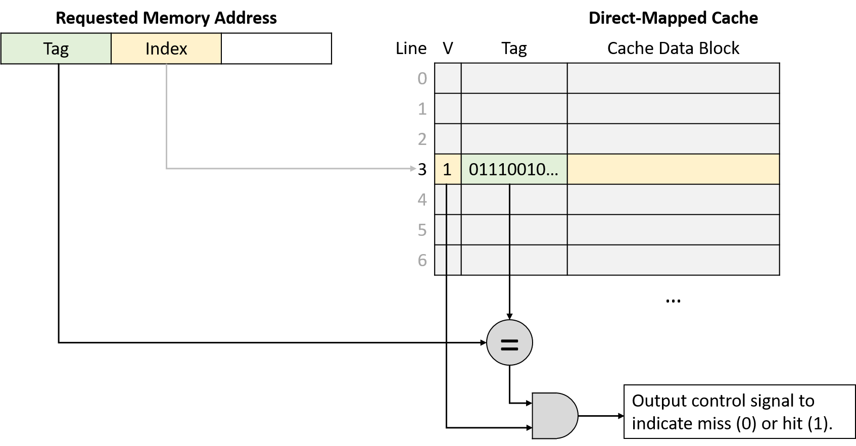
For a cache lookup to produce a hit, the tag field stored in the cache line must exactly match the tag portion (upper bits) of the program’s requested memory address. A tag mismatch indicates that a cache line’s data block does not contain the requested memory, even if the line stores valid data. Figure 3 illustrates how a cache divides a memory address into a tag and an index, uses the index bits to select a target cache line, verifies a line’s valid bit, and checks the line’s tag for a match.
Retrieving Cached Data
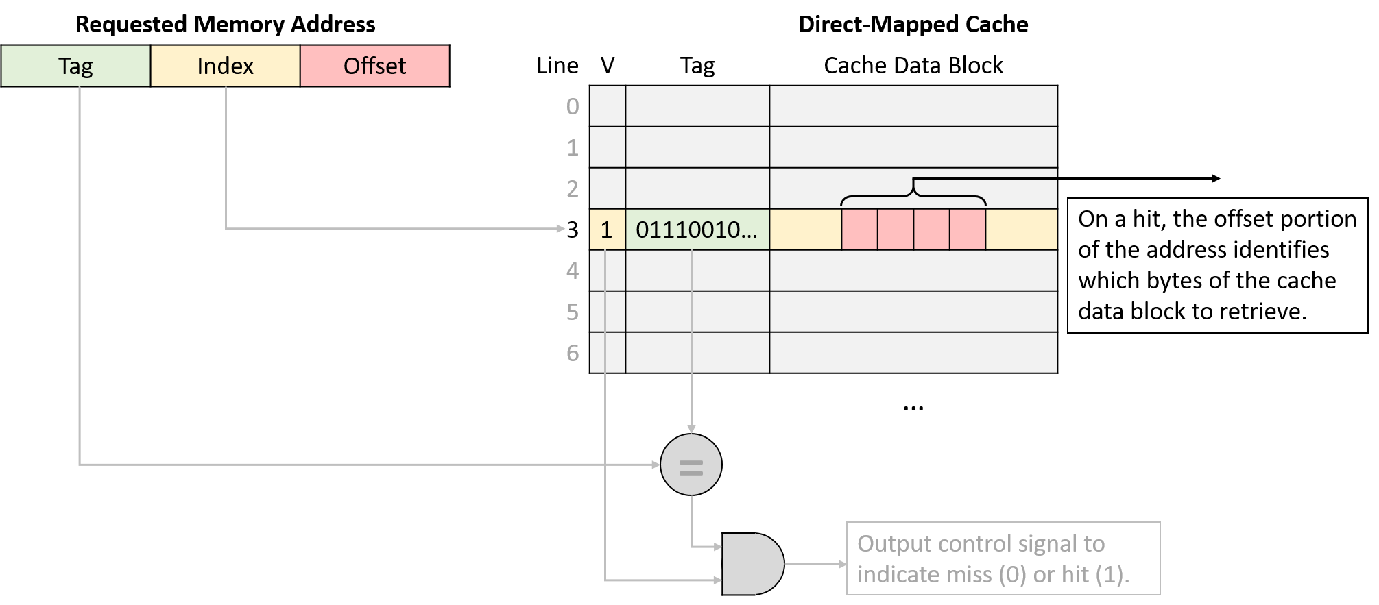
Finally, after using the program’s requested memory address to find the appropriate cache line and verifying that the line holds a valid subset of memory containing that address, the cache sends the requested data to the CPU’s components that need it. Because a cache line’s data block size (for example, 64 bytes) is typically much larger than the amount of data that programs request (for example, 4 bytes), caches use the low-order bits of the requested address as an offset into the cached data block. Figure 4 depicts how the offset portion of an address identifies which bytes of a cache block the program expects to retrieve.
Memory Address Division
The dimensions of a cache dictate how many bits to interpret as the offset, index, and tag portions of a memory address. Equivalently, the number of bits in each portion of an address imply what the dimensions of a cache must be. In determining which bits belong to each portion of an address, it’s helpful to consider the address from right to left (that is, from least to most significant bit).
The rightmost portion of the address is the offset, and its length depends on a cache’s block size dimension. The offset portion of an address must contain enough bits to refer to every possible byte within a cache data block. For example, suppose that a cache stores 32-byte data blocks. Because a program might come along asking for any of those 32 bytes, the cache needs enough offset bits to describe exactly which of the 32 possible positions the program might want. In this case, it would need five bits for the offset because five bits are necessary to represent 32 unique values (log232 = 5). In the reverse direction, a cache that uses four bits for the offset must store 16-byte data blocks (24 = 16).
The index portion of the address begins immediately to the left of the offset. To determine the number of index bits, consider the number of lines in the cache, given that the index needs enough bits to uniquely identify every cache line. Using similar logic to the offset, a cache with 1,024 lines needs 10 bits for the index (log2 1,024 = 10). Likewise, a cache that uses 12 bits for the index must have 4,096 lines (212 = 4,096).
The remaining address bits form the tag. Because the tag must uniquely identify the subset of memory contained within a cache line, the tag must use all of the remaining, unclaimed bits of the address. For example, if a machine uses 32-bit addresses, a cache with 5 offset bits and 10 index bits uses the remaining 32 - 15 = 17 bits of the address to represent the tag.
Direct-Mapped Read Examples
Consider a CPU with the following characteristics:
-
16-bit memory addresses
-
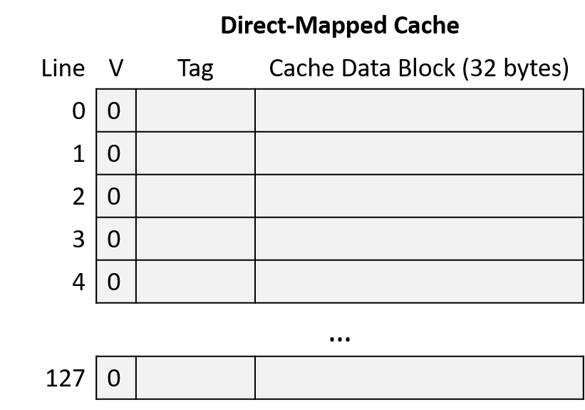
a direct-mapped cache with 128 cache lines
-
32-byte cache data blocks.
The cache starts empty (all lines are invalid), as shown in Figure 6.
Suppose that a program running on this CPU accesses the following memory locations:
-
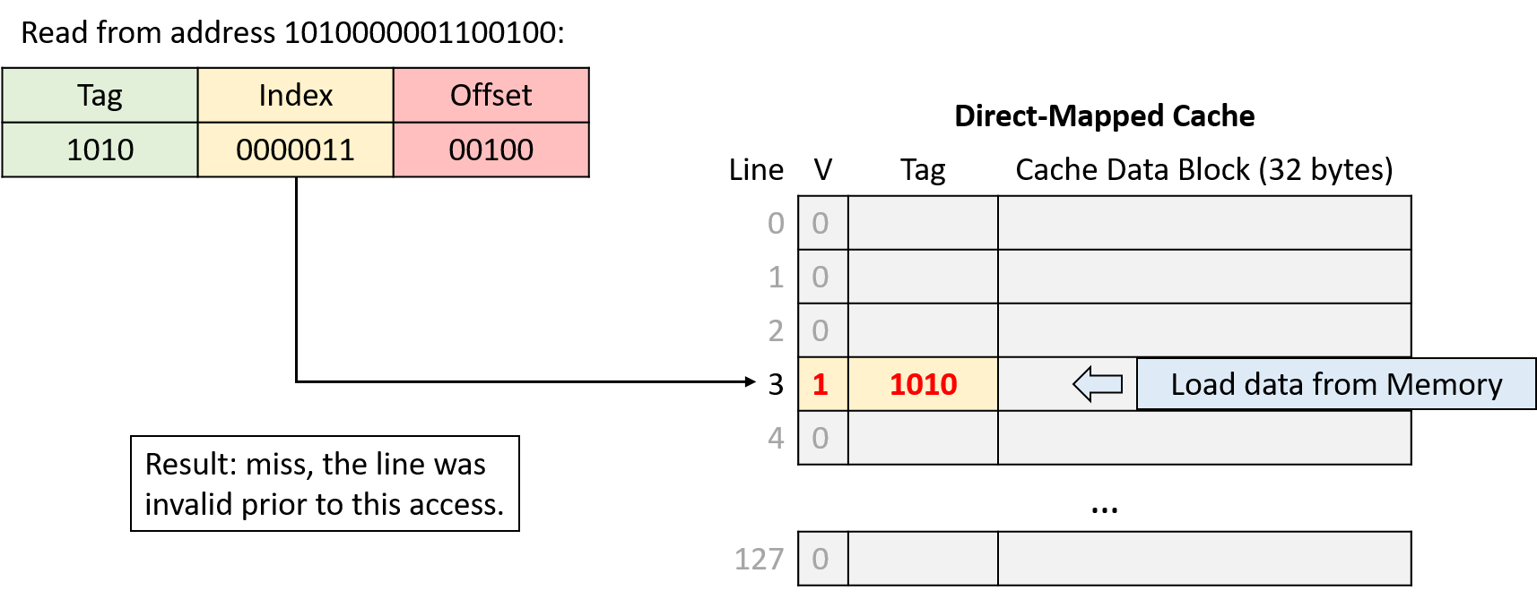
Read from address 1010000001100100
-
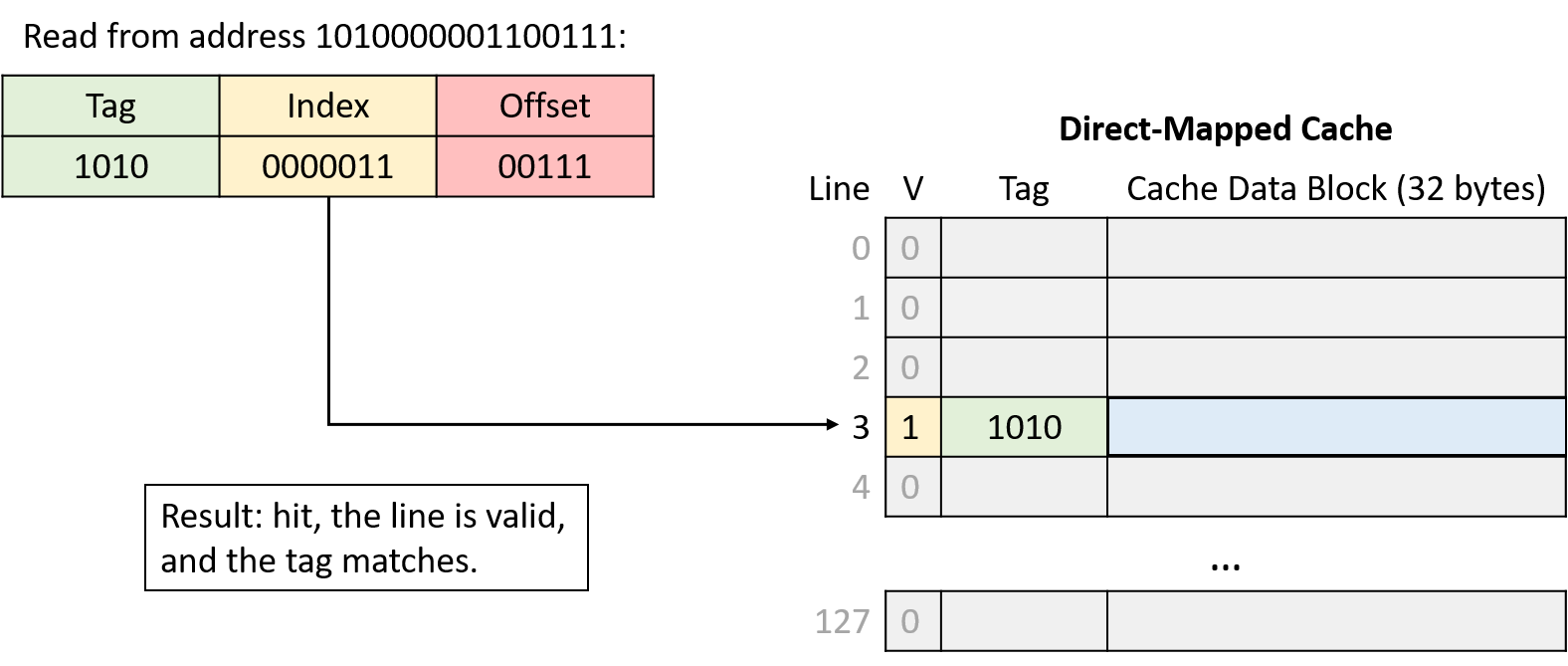
Read from address 1010000001100111
-
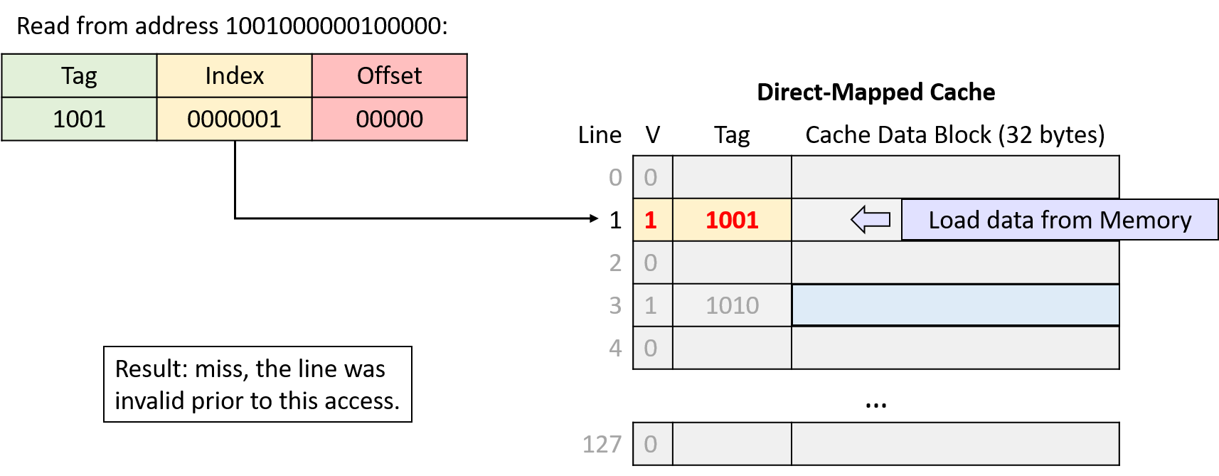
Read from address 1001000000100000
-
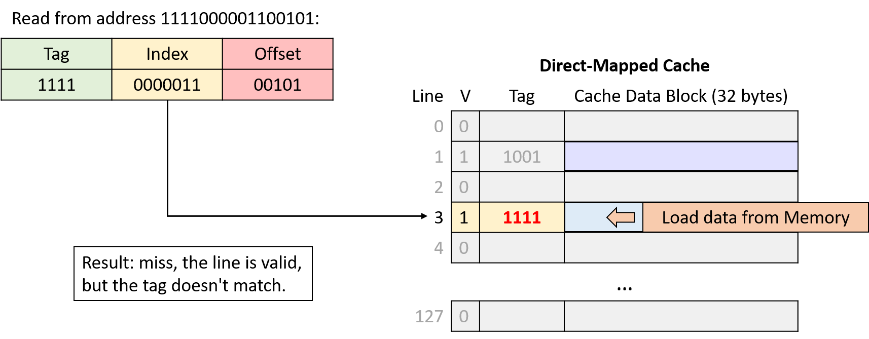
Read from address 1111000001100101
To put the entire sequence together, follow these steps when tracing the behavior of a cache:
-
Divide the requested address into three portions, from right (low-order bits) to left (high-order bits): an offset within the cache data block, an index into the appropriate cache line, and a tag to identify which subset of memory the line stores.
-
Index into the cache using the middle portion of the requested address to find the cache line to which the address maps.
-
Check the cache line’s valid bit. When invalid, the program can’t use a cache line’s contents (cache miss), regardless of what the tag might be.
-
Check the cache line’s tag. If the address’s tag matches the cache line’s tag and the line is valid, the cache line’s data block holds the data the program is looking for (cache hit). Otherwise, the cache must load the data from main memory at the identified index (cache miss).
-
On a hit, use the low-order offset bits of the address to extract the program’s desired data from the stored block. (Not shown in example.)
Address Division
Begin by determining how to divide the memory addresses into their offset, index, and tag portions. Consider the address portions from low-order to high-order bits (right to left):
-
Offset: A 32-byte block size implies that the rightmost five bits of the address (log2 32 = 5) comprise the offset portion. With five bits, the offset can uniquely identify any of the 32 bytes in block.
-
Index: A cache with 128 lines implies that the next seven bits of the address (log2 128 = 7) comprise the index portion. With seven bits, the index can uniquely identify each cache line.
-
Tag: The tag consists of any remaining address bits that don’t belong to the offset or index. Here, the address has four remaining bits left that form the tag (16 - (5 + 7) = 4).
Writing to Cached Data
So far, this section has primarily considered memory read operations for which a CPU performs lookups in the cache. Caches must also allow programs to store values, and they support store operations with one of two strategies.
-
In a write-through cache, a memory write operation modifies the value in the cache and simultaneously updates the contents of main memory. That is, a write operation always synchronizes the contents of the cache and main memory immediately.
-
In a write-back cache, a memory write operation modifies the value stored in the cache’s data block, but it does not update main memory. Thus, after updating the cache’s data, a write-back cache’s contents differ from the corresponding data in main memory.
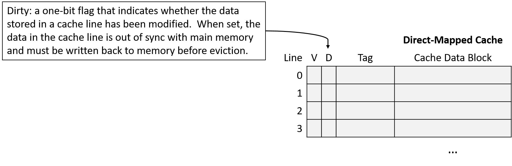
To identify cache blocks whose contents differ from their main memory counterparts, each line in a write-back cache stores an additional bit of metadata, known as a dirty bit. When evicting the data block from a dirty cache line, the cache block’s data must first be written back to main memory to synchronize their contents. Figure 11 shows a direct-mapped cache that includes a dirty bit to mark lines that must be written to memory upon eviction.
As usual, the difference between the designs reveals a trade-off. Write-through caches are less complex than write-back caches, and they avoid storing extra metadata in the form of a dirty bit for each line. On the other hand, write-back caches reduce the cost of repeated writes to the same location in memory.
For example, suppose that a program frequently updates the same variable without that variable’s memory ever being evicted from the cache. A write-through cache writes to main memory on every update, even though each subsequent update is just going to overwrite the previous one, whereas a write-back cache writes to memory only when eventually evicting the cache block. Because amortizing the cost of a memory access across many writes significantly improves performance, most modern caches opt for a write-back design.
Direct-Mapped Write Examples (Write-Back)
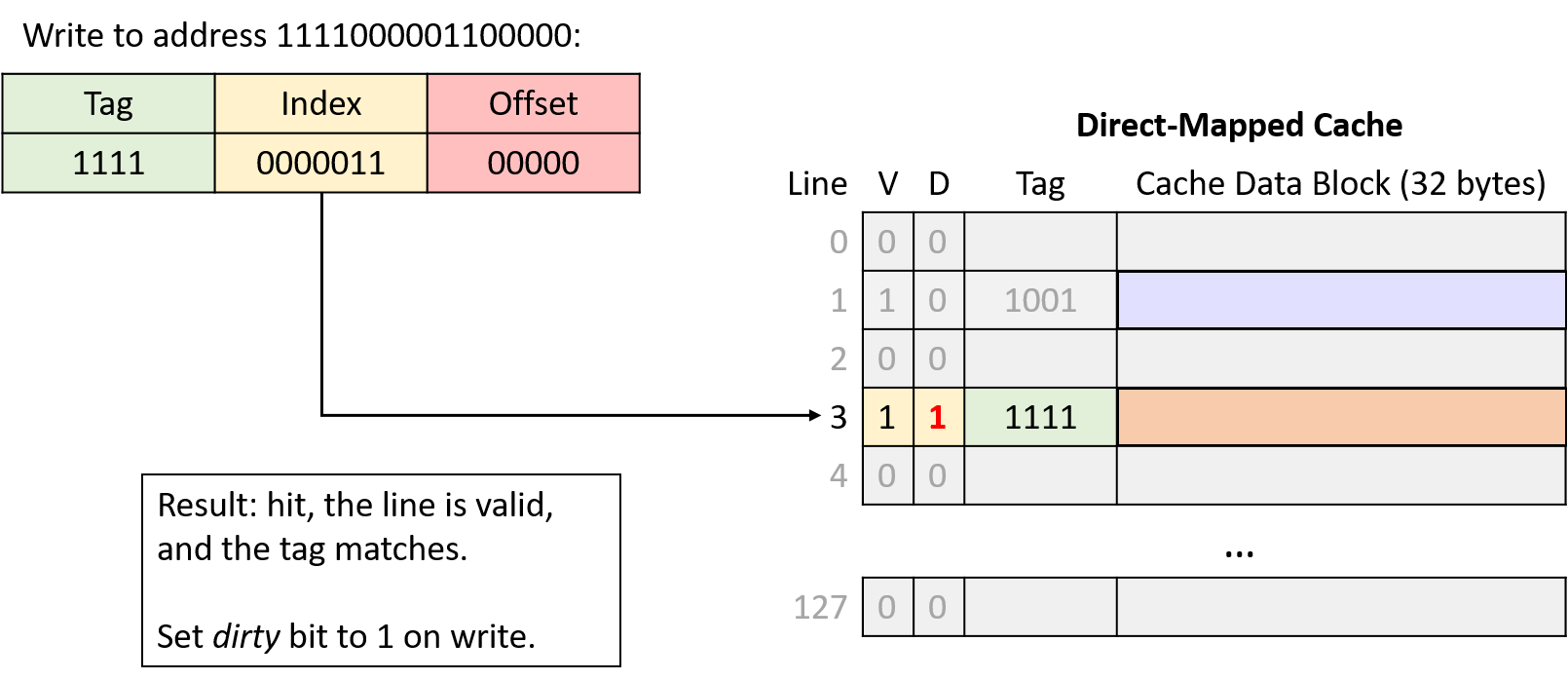
Writes to the cache behave like reads, except they also set the modified cache line’s dirty bit. When evicting a dirty cache line, the cache must write the modified data block to memory before discarding it.
Suppose that the example scenario described above continues with two additional memory accesses:
-
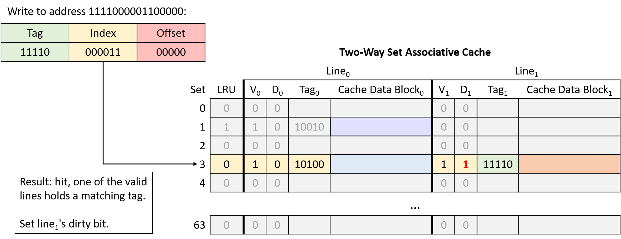
Write to address: 1111000001100000
-
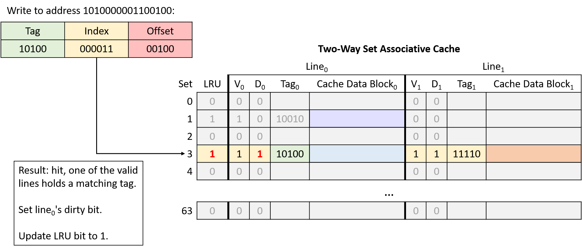
Write to address: 1010000001100100
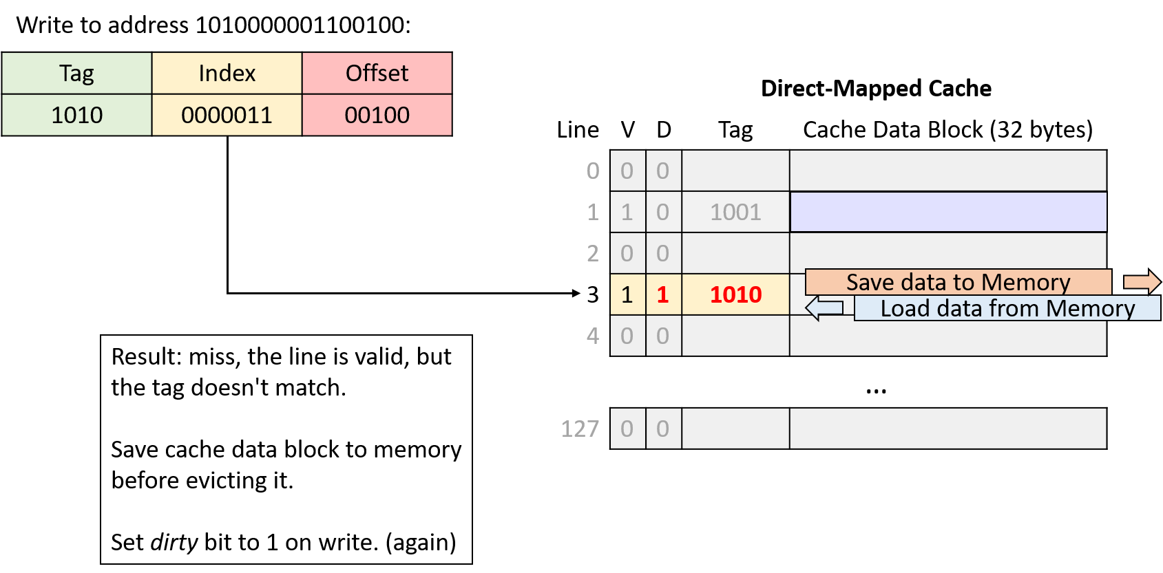
In the fourth and sixth memory accesses of the example, the cache evicts data because two memory regions are competing for the same cache line. Next, we’ll explore a different cache design that aims to reduce this type of competition.
11.4.2. Cache Misses and Associative Designs
Cache designers aim to maximize a cache’s hit rate to ensure that as many memory requests as possible can avoid going to main memory. Even though locality provides hope for achieving a good hit rate, real caches can’t expect to hit on every access for a variety of reasons:
-
Compulsory misses or cold-start misses: If a program has never accessed a memory location (or any location near it), it has little hope of finding that location’s data in the cache. Thus, programs often cannot avoid cache misses when first accessing new memory addresses.
-
Capacity misses: A cache stores a subset of main memory, and ideally, it stores exactly the subset of memory that a program is actively using. However, if a program is actively using more memory than fits in the cache, it can’t possibly find all of the data it wants in the cache, leading to misses.
-
Conflict misses: To reduce the complexity of finding data, some cache designs limit where in the cache data can reside, and those restrictions can lead to misses. For example, even if a direct-mapped cache is not 100% full, a program might end up with the addresses of two frequently used variables mapping to the same cache location. In such cases, each access to one of those variables evicts the other from the cache as they compete for the same cache line.
The relative frequency of each miss type depends on a program’s memory access pattern. In general though, without increasing the cache size, a cache’s design mainly affects its conflict miss rate. Although direct-mapped caches are less complex than other designs, they suffer the most from conflicts.
The alternative to a direct-mapped cache is an associative cache. An associative design gives a cache the flexibility to choose among more than one location to store a region of memory. Intuitively, having more storage location options reduces the likelihood of conflicts but also increases complexity due to more locations needing to be checked on every access.
A fully associative cache allows any memory region to occupy any cache location. Fully associative caches offer the most flexibility, but they also have the highest lookup and eviction complexity because every location needs to be simultaneously considered during any operation. Although fully associative caches are valuable in some small, specialized applications (for example, TLBs), their high complexity makes them generally unfit for a general-purpose CPU cache.
Set associative caches occupy the middle ground between direct-mapped and fully associative designs, which makes them well suited for general-purpose CPUs. In a set associative cache, every memory region maps to exactly one cache set, but each set stores multiple cache lines. The number of lines allowed in a set is a fixed dimension of a cache, and set associative caches typically store two to eight lines per set.
11.4.3. Set Associative Caches
A set associative design offers a good compromise between complexity and conflicts. The number of lines in a set limits how many places a cache needs to check during a lookup, and multiple memory regions that map to the same set don’t trigger conflict misses unless the entire set fills.
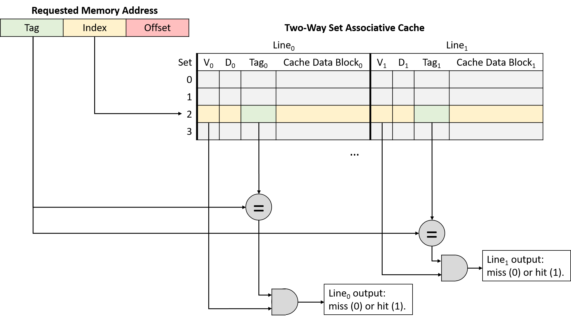
In a set associative cache, the index portion of a memory address maps the address to one set of cache lines. When performing an address lookup, the cache simultaneously checks every line in the set. Figure 14 illustrates the tag and valid bit checks in a two-way set associative cache.
If any of a set’s valid lines contains a tag that matches the address’s tag portion, the matching line completes the lookup. When the lookup narrows the search to just one cache line, it proceeds like a direct-mapped cache: the cache uses the address’s offset to send the desired bytes from the line’s cache block to the CPU’s arithmetic components.
The additional flexibility of multiple cache lines in a set reduces conflicts, but it also introduces a new wrinkle: when loading a value into a cache (and when evicting data already resident in the cache), the cache must decide which of the line options to use.
To help solve this selection problem, caches turn to the idea of locality. Specifically, temporal locality suggests that recently used data is likely to be used again. Therefore, caches adopt the same strategy that the previous section used to manage our example bookcase: when deciding which line in a set to evict, choose the least recently used (LRU) line. LRU is known as a cache replacement policy because it governs the cache’s eviction mechanism.
The LRU policy requires each set to store additional bits of metadata to identify which line of the set was used least recently. As the number of lines in a set increases, so does the number of bits required to encode the LRU status of the set. These extra metadata bits contribute to the "higher complexity" of set associative designs compared to simpler direct-mapped variants.
Figure 15 illustrates a two-way set associative cache, meaning each set contains two lines. With just two lines, each set requires one LRU metadata bit to keep track of which line was least recently used. In the figure, an LRU value of zero indicates the leftmost line was least recently used, and a value of one means the rightmost line was least recently used.
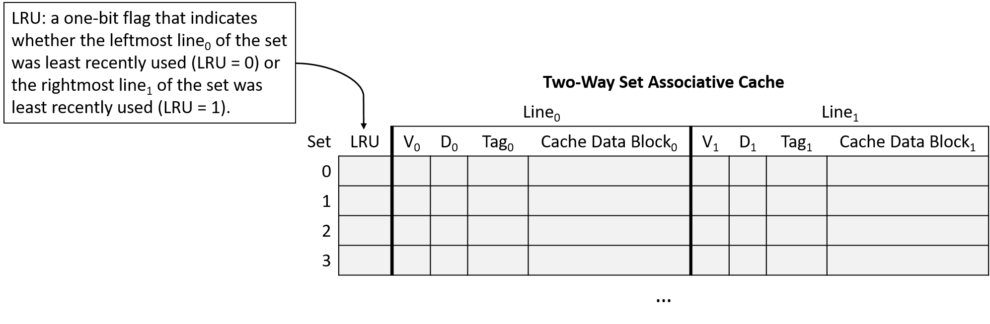
|
Figure 15's choice that zero means "left" and one means "right" is arbitrary. The interpretation of LRU bits varies across caches. If you’re asked to work with caches on an assignment, don’t assume the assignment is using the same LRU encoding scheme! |
Set Associative Cache Examples
Consider a CPU with the following characteristics:
-
16-bit memory addresses.
-
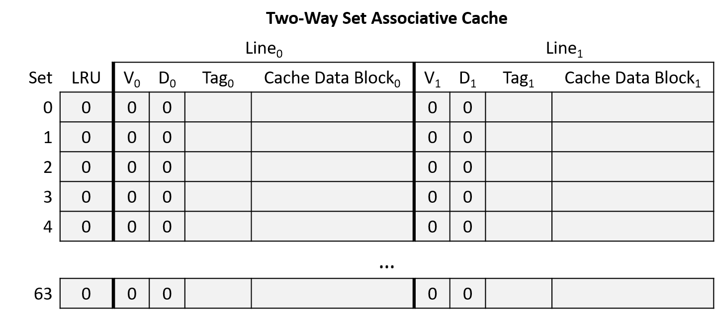
A two-way set associative cache with 64 sets. Note that making a cache two-way set associative doubles its storage capacity (two lines per set), so this example halves the number of sets so that it stores the same number of lines as the earlier direct-mapped example.
-
32-byte cache blocks.
-
An LRU cache replacement policy that indicates whether the leftmost line of the set was least recently used (LRU = 0) or the rightmost line of the set was least recently used (LRU = 1).
Initially, the cache is empty (all lines invalid and LRU bits 0), as shown in Figure 16.
Suppose that a program running on this CPU accesses the following memory locations (same as the direct-mapped example):
-
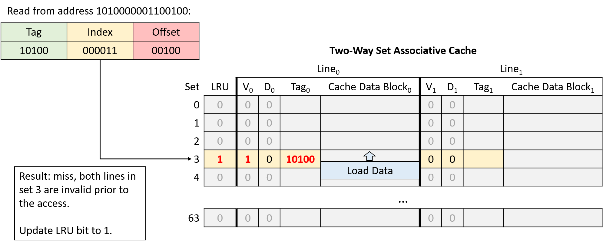
Read from address 1010000001100100
-
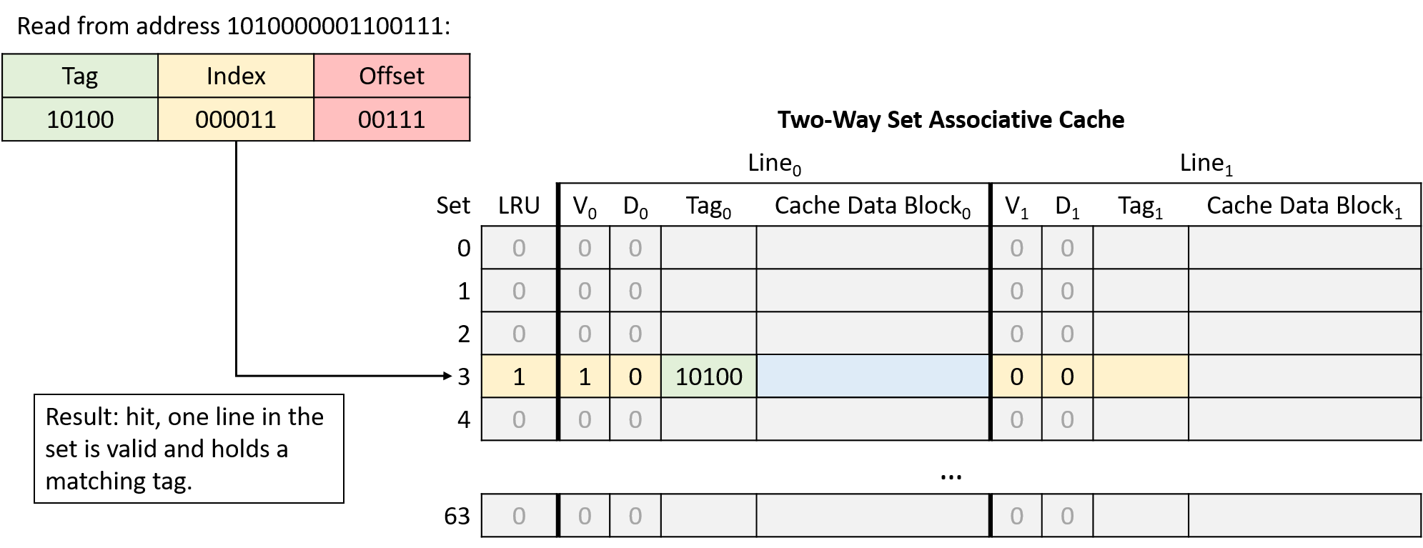
Read from address 1010000001100111
-
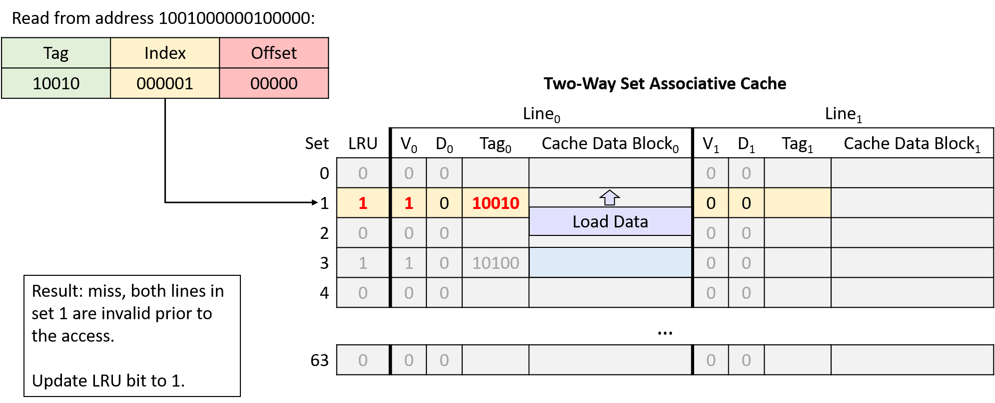
Read from address 1001000000100000
-
Read from address 1111000001100101
-
Write to address 1111000001100000
-
Write to address 1010000001100100
Address Division
Begin by determining how to divide the memory addresses into their offset, index, and tag portions. Consider the address portions from low-order to high-order bits (right to left):
-
Offset: A 32-byte block size implies that the rightmost five bits of the address (log2 32 = 5) comprise the offset portion. Five bits allows the offset to uniquely identify any of the bytes in a block.
-
Index: A 64-set cache implies that the next six bits of the address (log2 64 = 6) comprise the index portion. Six bits allows the index to uniquely identify each set in the cache.
-
Tag: The tag consists of any remaining bits of the address that don’t belong to the offset or index. Here, the address has five remaining bits left over for the tag (16 - (5 + 6) = 5).
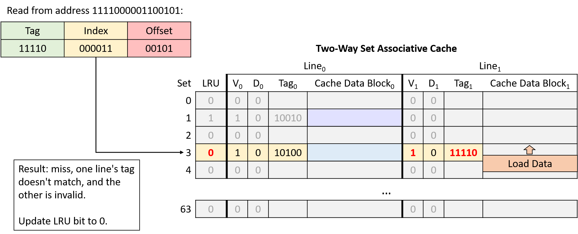
In this example, the same memory access sequence that produced two conflict misses with a direct-mapped cache suffers from no conflicts with a two-way set associative cache.