9.2. Common Instructions
In this section, we discuss several common ARM assembly instructions. Table 1 lists the most foundational instructions in ARM assembly.
| Instruction | Translation |
|---|---|
|
D = *(addr) (loads the value in memory into register D) |
|
*(addr) = S (stores S into memory location *(addr) ) |
|
D = S (copies value of S into D) |
|
D = O1 + O2 (adds O1 to O2 and stores result in D) |
|
D = O1 - O2 (subtracts O2 from O1 and stores result in D) |
Therefore, the sequence of instructions
str     w0, [sp, #12]
ldr     w0, [sp, #12]
add     w0, w0, #0x2
translates to:
-
Store the value in register
w0in the memory location specified bysp+ 12 (or*(sp + 12)). -
Load the value from memory location
sp+ 12 (or*(sp + 12)) into registerw0. -
Add the value 0x2 to register
w0, and store the result in registerw0(orw0=w0+ 0x2).
The add and sub instructions shown in Table 1 also assist with maintaining
the organization of the program stack (i.e., the call stack). Recall that the
stack pointer (sp) is reserved by the compiler for call stack management.
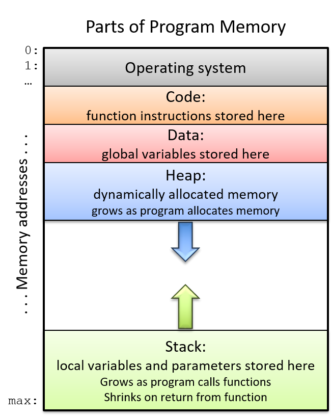
Recall also from our earlier discussion on
program memory that
the call stack typically stores local variables and parameters and
helps the program track its own execution (see Figure 1). On ARM
systems, the execution stack grows toward lower addresses. Like all stack
data structures, operations occur at the "top" of the call stack; sp
therefore "points" to the top of the stack, and its value is the address of
top of the stack.
The ldp and stp instructions shown in Table 2 assist with moving
multiple memory locations, usually either on or off the program stack.
In Table 2, the register x0 holds a memory address.
| Instruction | Translation |
|---|---|
|
D1 = *(x0), D2 = *(x0+8) (loads the value at x0 and x0+8 into registers D1 and D2, respectively) |
|
x0 = x0 + 0x10, then sets D1 = *(x0), D2 = *(x0+8) |
|
D1 = *(x0), D2 = *(x0+8), then sets x0 = x0 + 0x10 |
|
*(x0) = S1, *(x0+8) = S2 (stores S1 and S2 at locations *(x0) and *(x0+8), respectively) |
|
sets x0 = x0 - 16, then stores *(x0) = S1, *(x0+8) = S2 |
|
stores *(x0) = S1, *(x0+8) = S2 then sets x0 = x0 - 16 |
In short, the ldp instruction loads a pair of values from the memory
locations held in register x0 and at an offset of eight from that memory location
(i.e., x0 + 0x8) into the destination registers D1 and D2, respectively.
Meanwhile, the stp instruction stores the pair of values in source registers
S1 and S2 to the memory locations held in register x0 and at an offset of
eight from that address (i.e., x0 + 0x8). Note that the assumption here is that
values in the registers are 64-bit quantities. If 32-bit registers are being
used instead, the memory offsets change to x0 and x0 + 0x4 respectively.
There are also two special forms of the ldp and stp instructions that
enable simultaneous updates to x0. For example, the instruction stp S1, S2,
[x0, #-16]! implies that 16 bytes should first be subtracted from x0, and
only afterward should S1 and S2 be stored at the offsets [x0] and [x0+0x8].
In contrast, the instruction ldp D1, D2, [x0], #0x10 states that the values
at offsets [x0] and [x0+8] should first be stored in destination registers D1
and D2 and only afterward should x0 have 16 bytes added to it. These
special forms are commonly used at the beginning and end of functions that have
multiple function calls, as we will see
later.
9.2.1. Putting It All Together: A More Concrete Example
Let’s take a closer look at the adder2 function
//adds two to an integer and returns the result
int adder2(int a) {
    return a + 2;
}
and its corresponding assembly code:
0000000000000724 <adder2>:
 724:   d10043ff        sub     sp, sp, #0x10
 728:   b9000fe0        str     w0, [sp, #12]
 72c:   b9400fe0        ldr     w0, [sp, #12]
 730:   11000800        add     w0, w0, #0x2
 734:   910043ff        add     sp, sp, #0x10
 738:   d65f03c0        ret
The assembly code consists of a sub instruction, followed by str and
ldr instructions, two add instructions, and finally a ret instruction.
To understand how the CPU executes this set of instructions, we need to
revisit the structure of
program memory.
Recall that every time a program executes, the operating system allocates the
new program’s address space (also known as virtual memory).
Virtual memory and the related concept of
processes are covered in greater detail in
Chapter 13; for now, it suffices to think of a process as the abstraction of a
running program and virtual memory as the memory that is allocated to a single
process. Every process has its own region of memory called the call stack.
Keep in mind that the call stack is located in process/virtual memory, unlike
registers (which are located in the CPU).
Figure 2 depicts a sample state of the call stack and registers prior
to the execution of the adder2 function.
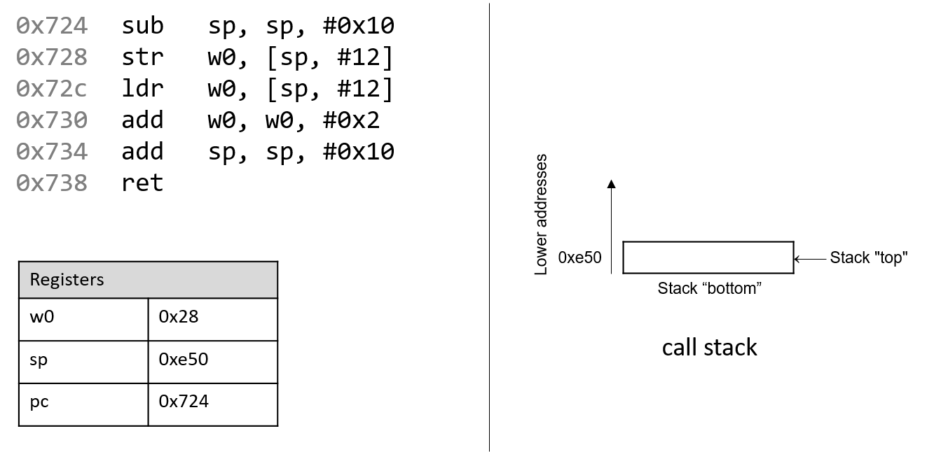
Notice that the stack grows toward lower addresses. The parameter to the
adder2 function (or a) is stored in register x0 by convention. Since
a is of type int, it is stored in component register w0, as shown
in Figure 2. Likewise, since the adder2 function returns an int,
component register w0 is used for the return value instead of x0.
The addresses associated with the instructions in the code segment of program memory have been shortened to 0x724-0x738 to improve figure readability. Likewise, the addresses associated with the call stack segment of program memory have been shortened to 0xe40-0xe50 from a range of 0xffffffffee40 to 0xffffffffee50. In truth, call stack addresses occur at much higher addresses in program memory than code segment addresses.
Pay close attention to the initial values of registers sp and
pc: they are 0xe50 and 0x724, respectively. The pc register
(or program counter) indicates the next instruction to execute, and the address
0x724 corresponds to the first instruction in the adder2 function.
The red (upper-left) arrow in the following figures visually indicates the currently executing instruction.
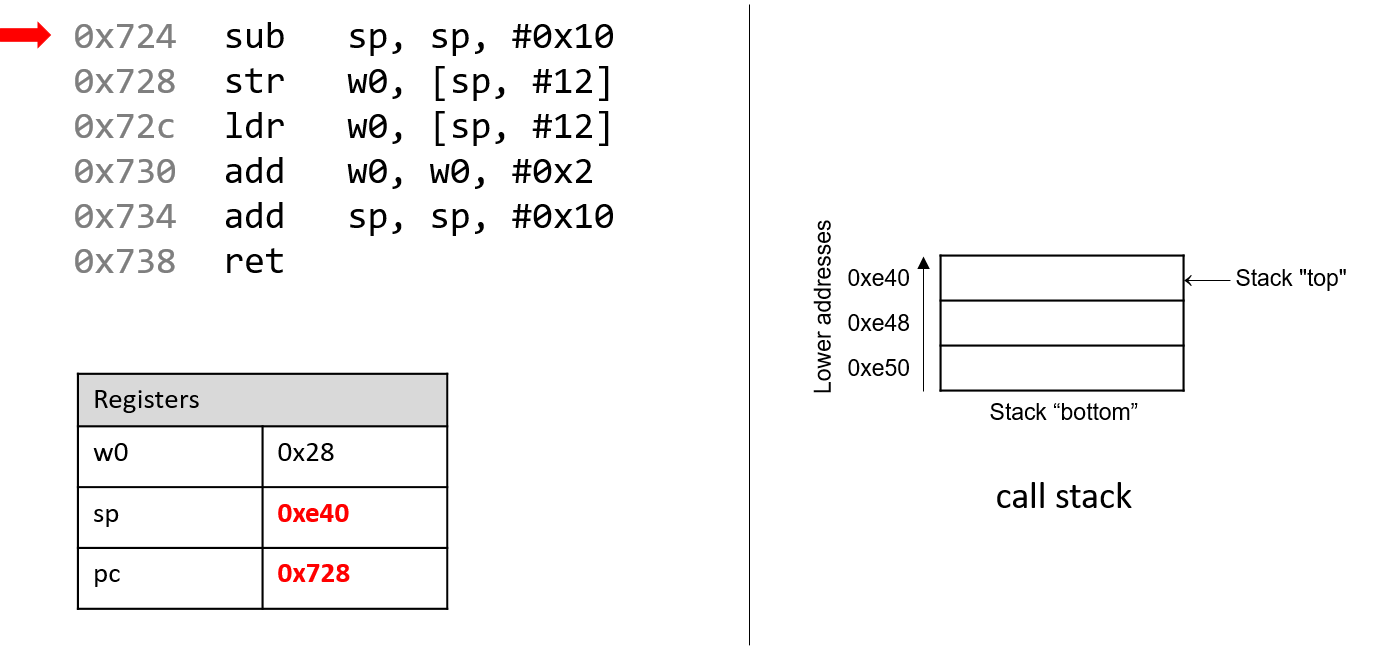
The first instruction (sub sp, sp, #0x10) subtracts the constant value
0x10 from the stack pointer, and updates the stack pointer with the new
result. Since the stack pointer contains the address of the top of the stack,
this operation grows the stack by 16 bytes. The
stack pointer now contains the address 0xe40, whereas the program counter
(pc) register contains the address of the next instruction to execute,
or 0x728.
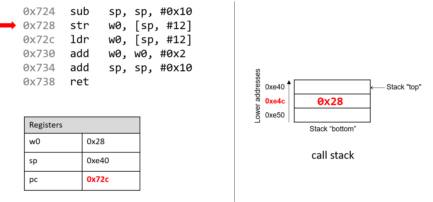
Recall that the str instruction stores a value located in a register into
memory. Thus, the next instruction (str w0, [sp, #12]) places the value
in w0 (the value of a, or 0x28) at call stack location sp + 12, or
0xe4c. Note that this instruction does not modify the contents of register
sp in any way; it simply stores a value on the call stack. Once this
instruction executes, pc advances to the address of the next instruction,
or 0x72c.
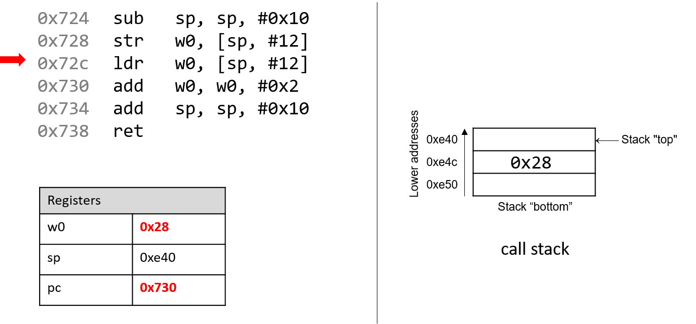
Next, ldr w0, [sp, #12] executes. Recall that the ldr instruction loads
a value in memory into a register. By executing this instruction, the CPU
replaces the value in register w0 with the value located at stack address
sp + 12. Even though this may seem like a nonsensical operation (0x28 is
replaced by 0x28, after all), it highlights a convention where the compiler
typically stores function parameters onto the call stack for later use and
then reloads them into registers as needed. Again, the value stored in the
sp register is not affected by the str operation. As far as the
program is concerned, the "top" of the stack is still 0xe40. Once the
ldr instruction executes, pc advances to address 0x730.
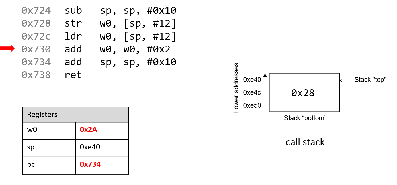
Afterward, add w0, w0, #0x2 executes. Recall that the add instruction
has the form add D, O1, O2 and places O1 + O2 in the destination register
D. So, add w0, w0, #0x2 adds the constant value 0x2 to the value
stored in w0 (0x28), resulting in 0x2A being stored in register w0.
Register pc advances to the next instruction to be executed, or 0x734.
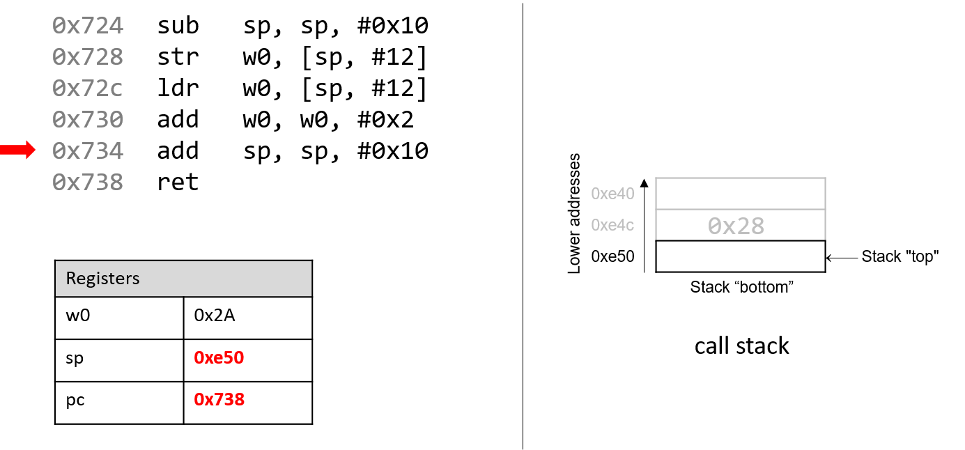
The next instruction that executes is add sp, sp, #0x10. This instruction
adds 16 bytes to the address stored in sp. Since the stack grows toward
lower addresses, adding 16 bytes to the stack pointer consequently shrinks
the stack, and reverts sp to its original value of 0xe50. The pc
register then advances to 0x738.
Recall that the purpose of the call stack is to store the temporary data that
each function uses as it executes in the context of a larger program. By
convention, the stack "grows" at the beginning of a function call, and
reverts to its original state when the function ends. As a result, it is
common to see a sub sp, sp, #v instruction (where v is some constant
value) at the beginning of a function, and add sp, sp, #v at the end.
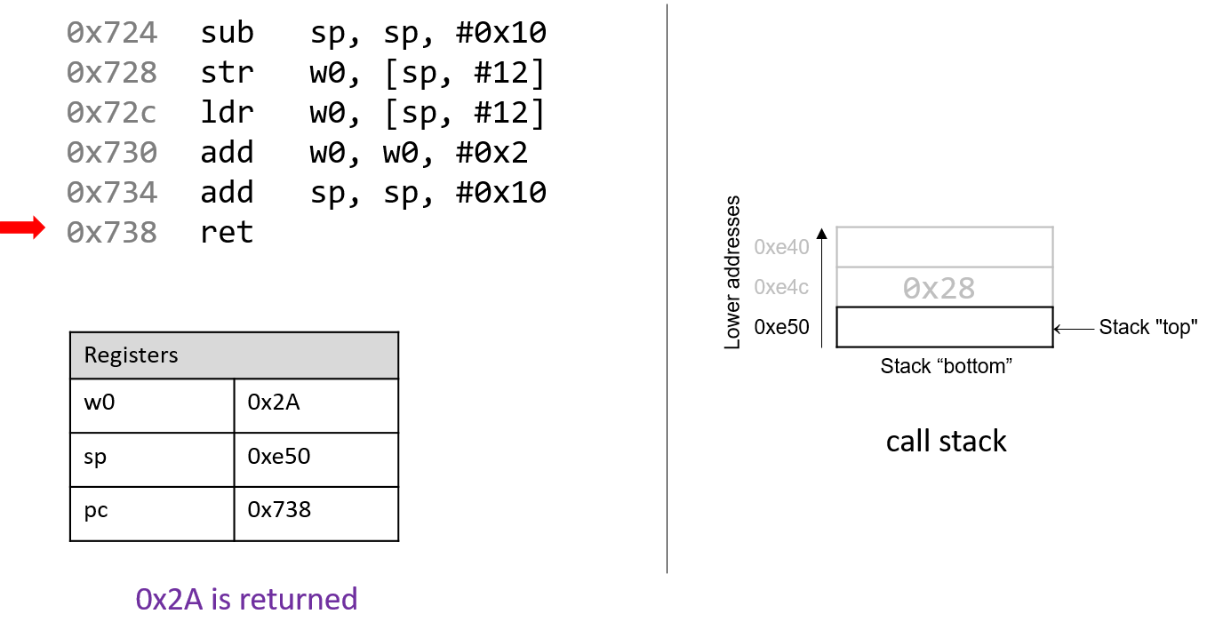
The last instruction that executes is ret. We will talk more about what
ret does in future sections when we discuss function calls, but
for now it suffices to know that ret prepares the call stack for
returning from a function. By convention, the register x0 always contains
the return value (if one exists). In this case, since adder2 is of type
int, the return value is stored in component register w0 and the function
returns the value 0x2A, or 42.