9.1. Diving into Assembly: Basics
For a first look at assembly, we modify the adder function from the
assembly introduction chapter to
simplify its behavior. The modified function (adder2) is shown here:
#include <stdio.h>

//adds two to an integer and returns the result
int adder2(int a) {
    return a + 2;
}

int main(void) {
    int x = 40;
    x = adder2(x);
    printf("x is: %d\n", x);
    return 0;
}
To compile this code, use the following command:
$ gcc -o adder adder.c
Next, let’s view the corresponding assembly of this code by using the
objdump command:
$ objdump -d adder > output
$ less output
Search for the code snippet associated with adder2 by typing /adder while examining
the file output using less. The section associated with adder should look
similar to the following:
adder2 function0000000000000724 <adder2>: 724: d10043ff sub sp, sp, #0x10 728: b9000fe0 str w0, [sp, #12] 72c: b9400fe0 ldr w0, [sp, #12] 730: 11000800 add w0, w0, #0x2 734: 910043ff add sp, sp, #0x10 738: d65f03c0 ret
Don’t worry if you don’t understand what’s going on just yet. We will cover assembly in greater detail in future sections. For now, let’s study the structure of these individual instructions.
Each line in the preceding example contains the instruction’s 64-bit address in
program memory (shortened to the lowest three digits to save space),
the bytes corresponding to the instruction, and the plain-text
representation of the instruction itself. For example, d10043ff is the
machine code representation of the instruction sub sp, sp, #0x10, and
the instruction occurs at address 0x724 in code memory. Note that
0x724 is an abbreviation of the full 64-bit address associated with the
sub sp, sp #0x10 instruction; objdump omits the leading zeros to
help with readability.
It is important to note that a single line of C code often translates to
multiple instructions in assembly. The operation a + 2 is represented by the
three instructions at code memory addresses 0x728 through 0x730:
str w0, [sp, #12], ldr w0, [sp, #12], and add w0, w0, #0x2.
|
Your assembly may look different!
If you are compiling your code along with us, you may notice that some of your assembly examples look different. The precise assembly instructions that are output by a compiler depend on the generating compiler’s version, the precise architecture, and the underlying operating system. Most of the assembly examples in this chapter were generated on a Raspberry Pi 3B+ running the 64-bit Ubuntu Mate operating system and using GCC. If you use a different operating system, a different compiler, or a different Raspberry Pi or single-board computer, your assembly output may vary. In the examples that follow, we do not use any optimization flags. For example,
we compile any example file (e.g. |
9.1.1. Registers
Recall that a register is a word-sized storage unit located directly on the
CPU. The ARMv8 CPU has a total of 31 registers for storing general-purpose 64-bit
data: x0 to x30. Whereas a program may interpret a
register’s contents as integers or as addresses, the register itself makes no
distinction. Programs can read from or write to all 31 registers.
The ARMv8-A ISA also specifies special-purpose registers. The first two worth
noting are the stack pointer register (sp) and the program counter
register (pc). The compiler reserves the sp register for maintaining the
layout of the program stack. The pc register points to the next instruction
to be executed by the CPU; unlike the other registers, programs cannot write
directly to the pc register. Next, the zero register zr permanently
stores the value 0, and is only useful as a source register.
9.1.2. Advanced Register Notation
Since ARMv8-A is an extension of the 32-bit ARMv7-A architecture, the A64 ISA
provides mechanisms to access the lower 32 bits of each of the general-purpose
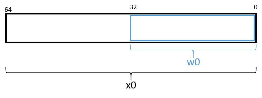
registers, or w0 through w30. Figure 1 shows a sample layout of register
x0. If 32-bit data is stored in component register w0, then the upper 32 bits
of the register become inaccessible, and are zeroed out.
|
The compiler may choose component registers depending on type
When reading assembly code, keep in mind that the compiler typically uses the
64-bit registers when dealing with 64-bit values (e.g., pointers or |
For readers previously familiar with the A32 ISA, it is important to note
that the 32-bit general-purpose registers r0 to r12 from the A32 ISA
map to the A64 component registers w0 to w12. The A64 ISA more than
doubles the number of available registers.
9.1.3. Instruction Structure
Each instruction consists of an operation code (or opcode) that specifies what it does, and one or more operands that tells the instruction how to do it. For most A64 instructions, the following format is typically used:
opcode D, O1, O2
Where opcode is the operation code, D is the destination register, O1 is
the first operand, and O2 the second operand. For example, the instruction
add w0, w0, #0x2 has the opcode add, a destination register of w0, and
the two operands w0 and #0x2. There are multiple types of operands:
-
Constant (literal) values are preceded by the
#sign. For example, in the instructionadd w0, w0, #0x2, the operand#0x2is a literal value that corresponds to the hexadecimal value 0x2. -
Register forms refer to individual registers. The instruction
add sp, sp, #0x10uses the stack pointer registerspto designate the destination register and the first of the two operands needed for theaddinstruction. -
Memory forms correspond to some value inside main memory (RAM) and are commonly used for address lookups. Memory address forms can contain a combination of registers and constant values. For example, in the instruction
str w0, [sp, #12], the operand[sp, #12]is an example of a memory form. It loosely translates to "add 12 to the value in registersp, and then perform a memory lookup on the corresponding address." If this sounds like a pointer dereference, that’s because it is!
9.1.4. An Example with Operands
The best way to explain operands in detail is to present a quick example. Suppose that memory contains the following values:
| Address | Value |
|---|---|
0x804 |
0xCA |
0x808 |
0xFD |
0x80c |
0x12 |
0x810 |
0x1E |
Let’s also assume that the following registers contain the values:
| Register | Value |
|---|---|
|
0x804 |
|
0xC |
|
0x2 |
|
0x4 |
Then the operands in Table 1 evaluate to the values shown there. Each row of the table matches an operand with its form (e.g., constant, register, memory), how it is translated, and its value.
| Operand | Form | Translation | Value |
|---|---|---|---|
|
Register |
|
0x804 |
|
Memory |
*(0x804) |
0xCA |
|
Constant |
0x804 |
0x804 |
|
Memory |
*( |
0x12 |
|
Memory |
*( |
0x1E |
|
(Sign-Extend) Memory |
*( |
0xFD |
|
Scaled Memory |
*( |
0x12 |
|
(Sign-Extend) Scaled Memory |
*( |
0x12 |
In Table 1, the notation x0 indicates the value stored in 64-bit
register x0, whereas w3 indicates a 32-bit value stored in component register
w3. The operand [x0] indicates that the value inside x0 should be
treated as an address, and to dereference (look up) the value at that address.
Therefore, the operand [x0] corresponds to *(0x804) or the value 0xCA. An
operation on a 32-bit register can be combined with a 64-bit register using
the sign-extend word (SXTW) instruction. So, [x0, w3, SXTW] sign extends
w3 into a 64-bit value before adding it to x0 and performing a memory
lookup. Lastly, scaled memory types enable the calculation of offsets
through the use of a left shift.
A few important notes before continuing. Although Table 1 shows many valid operand forms, not all forms can be used interchangeably in all circumstances.
Specifically:
-
Data cannot be read or written to memory directly; instead, ARM follows a load/store model, which requires data to be operated on in registers. Thus, data must be transferred to registers before being operated on, and transferred back to memory after the operations are complete.
-
The destination component of an instruction must always be a register.
Table 1 is provided as a reference; however, understanding key operand forms will help improve the reader’s speed in parsing assembly language.